For two decades, I've watched proximity sensors fail in ways the manuals never mention. The glossy datasheet specs—sensing distance, repeat accuracy, IP rating—are a fantasy in the real world of grinding metal dust, hydraulic fluid baths, and electromagnetic chaos. Let's move past the basics and into the gritty reality where these components live or die.
Experience Correction: The Gaps Between Lab Specs and Mill Floor Reality
The most glaring deviation is in nominal sensing distance. A sensor rated for 15mm will not achieve that with a hot, vibrating, oil-coated target. In practice, expect a 30-50% effective reduction. Temperature is the silent killer. Operating at the upper limit of the stated range, say 70°C, doesn't just reduce lifespan; it induces signal drift. I've documented inductive sensors drifting by up to 0.5mm at sustained high temperatures, enough to cause false triggers in precision assembly. The IP67/IP68 rating for washdown is another misnomer. It assumes clean water at room temperature and specific pressure. Hit that same sensor with a 180°F caustic cleaner or high-pressure steam, and the seals will degrade within weeks, not years. Vibration resistance ratings are tested for sinusoidal patterns. The random, multi-axis shock from a stamping press or forging hammer creates resonant frequencies that can crack internal potting compounds or loosen cores, leading to intermittent failure that is nearly impossible to diagnose.
Boundary Conditions: When to Walk Away
Knowing when not to use a standard proximity sensor is more critical than selecting one. Here are the red zones:
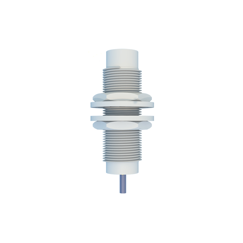
1. Ferrous Dust or Swarf Environments: Inductive sensors are magnets for fine ferrous particles. These particles adhere to the active face, gradually dampening the electromagnetic field and reducing sensing distance to zero. No amount of sealing prevents this; it's a fundamental physics problem. In such environments, like CNC lathe chip management, optical or capacitive sensors with frequent cleaning cycles are the only viable option.
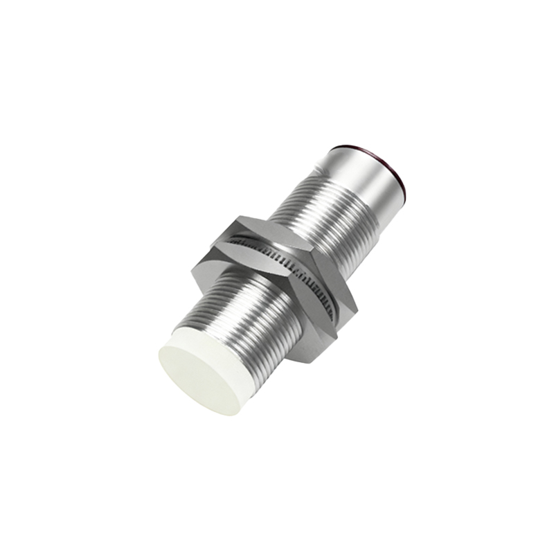
2. High-Speed Non-Ferrous Target Detection: Detecting aluminum cans or plastic bottles on a conveyor at speeds above 2m/s with a standard inductive sensor is a fool's errand. Eddy currents in non-ferrous metals are weak, requiring specialized models. Even then, consistent detection at high speed is unreliable due to the damped oscillation response. A photoelectric sensor is almost always superior here.
3. Direct Welding Cell Vicinity: The electromagnetic interference (EMI) from resistance welders is catastrophic. It's not just about physical distance; it's about the path of ground currents. I've seen sensors 10 meters away fail due to ground loops carrying weld current. The transient can induce voltages exceeding 1000V, frying the sensor's ASIC instantly. In these areas, you need sensors with extreme EMI immunity (often specified for welding environments) and dedicated, isolated grounding.
4. Extreme Static Charge Environments: In paper, plastic, or textile handling, static charges can reach tens of kilovolts. This charge can arc to the sensor face, not necessarily causing immediate failure but degrading the input circuit over time, leading to increased sensitivity drift and eventual breakdown.
Counterintuitive Conclusions: Data-Driven Insights That Defy Common Wisdom
1. A More Expensive Sensor Can Be Less Reliable: A high-precision, ultra-short-range sensor with a 0.1mm repeatability is a masterpiece of engineering. It's also incredibly fragile. In a high-vibration environment, its complex, sensitive circuitry will fail faster than a rugged, lower-accuracy unit. Sometimes, "dumber and tougher" wins. I have lifecycle data showing a standard 5mm range sensor outlasting a precision 2mm sensor by 300% in a packaging machine.
2. Shielding Can Make Interference Worse: The instinct when facing EMI is to specify a shielded (flush-mountable) inductive sensor. However, in environments with multiple sensors in close proximity, shielded sensors create "dead zones" for each other. Their lateral sensing fields are minimal. An unshielded sensor has a larger lateral field, which can be tuned to prevent mutual interference through careful spacing and mounting—a paradox where less shielding offers better multi-sensor integration.
3. The "Fail-Safe" State is Often Wrongly Configured: Most engineers default to configuring a sensor's output to go to a "0" state (off) on failure or loss of signal, considering it safe. In critical stop circuits, this is dangerous. If a wire is cut, the system sees a "safe" off signal. The correct approach is to use a normally closed (NC) configuration or a pulsed-output safety sensor so that wire break