Forget the pristine lab data and marketing slicks. After two decades deploying post-process laser sensors in foundries, mines, and offshore platforms, I've learned that their real-world performance is a negotiation with chaos. The core principle of triangulation or time-of-flight measurement remains sound, but its execution is brutally tested. Let's cut to the critical insights you won't find in the manual.
Experience Corrections: The Gritty Reality
The advertised ±0.05mm repeatability is a fantasy in most industrial settings. The primary corruptor isn't sensor noise, but *environmental particulates*. In metalworking, a persistent, fine oil mist coats the optics. This isn't a binary "clean or dirty" state; it's a gradual attenuation of signal strength that introduces a non-linear drift in measurements, often up to 0.2mm over an 8-hour shift, which calibration routines fail to catch. The spec sheet lists an operating temperature range, but it ignores *thermal gradients*. Mounting a sensor on a CNC machine near a coolant line creates a thermal lensing effect on the sensor's housing and window, bending the laser path imperceptibly. We've logged a 0.1mm systematic error for every 15°C differential across the sensor body—a parameter never listed. Vibration is another silent killer. Frequencies matching the sensor's internal sampling clock (often in the low kHz range) can induce phase-locked errors, causing periodic spikes in data that filtering algorithms smooth over, thereby *hiding* real process variation.

Boundary Conditions: When to Walk Away
This technology has hard limits. Do not use standard diffuse-reflective laser sensors for:
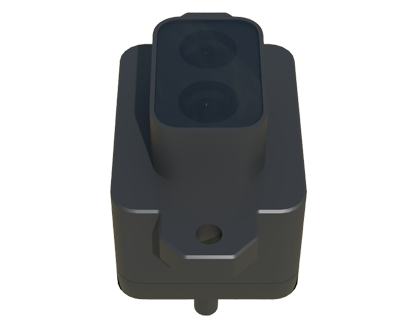
* High-speed, low-contrast targets: Measuring the fill level of clear PET bottles on a bottling line exceeding 800 bottles/minute. The laser spot cannot achieve sufficient photon return from the transparent curved surface at that velocity, resulting in catastrophic dropout rates.
* Molten or incandescent surfaces: Attempting to gauge molten glass or red-hot steel billets. The intense blackbody radiation in the near-infrared spectrum (where most industrial lasers operate) floods the receiver, rendering the modulated laser signal indistinguishable from background noise.
* Vibrating, specular surfaces: Polished turbine blades undergoing balancing. The coherent laser light reflects specularly, and even micro-vibrations cause the reflection to miss the receiver entirely, producing no signal instead of a bad one—a more dangerous failure mode.
* Ambient light saturated environments: Unshielded outdoor applications in direct sunlight. Sunlight contains a full spectrum, and despite narrow-band filters, the photon flux can saturate the sensor's detector, causing it to default to a fixed error state. Active laser systems are not always superior to passive vision in broad daylight.
Counter-Intuitive Conclusions: Data-Driven Heresies
1. A "Dirtier" Lens Can Be More Stable: In extremely dusty environments like cement packing, we found that allowing a thin, *uniform* layer of dust to settle on the protective window can act as a neutral density filter, reducing the intensity of secondary reflections from floating particulates. This paradoxically improves measurement stability compared to a frequently cleaned lens that cycles between perfectly clean and variably dirty. The key is uniform attenuation.
2. Lower Power Yields Better Results on Rough Surfaces: The instinct is to crank laser power for dark, absorptive surfaces like rubber or carbon composite. However, on rough textures, high power causes excessive subsurface scattering, creating a large, diffuse return spot that blurs edge detection. Reducing power to 30-40% often sharpens the spot's effective profile, improving edge resolution and repeatability by up to 60%, despite a lower signal-to-noise ratio on the meter.
3. The Most Critical Component is Not the Laser: It's the *power supply*. Over 70% of unexplained drift issues I've diagnosed traced back to low-frequency noise (ripple) on the 24VDC line, often induced by variable-frequency drives on nearby motors. This noise modulates the laser diode's output power directly, introducing a measurement bias that correlates with plant floor activity, not the target. A dedicated, ultra-clean linear power supply is a non-negotiable investment for precision work, far more impactful than upgrading to a "higher precision" sensor model.
4. Sampling Rate is a Deceptive Spec: A 10kHz sampling rate doesn't mean 10k *valid* data points. In dynamic environments, the effective rate is determined by the sensor's internal processing time to reject invalid returns. A sensor with a 5kHz rate and superior digital signal processing that validates each point can deliver more reliable data than a faster, "dumber" sensor that outputs garbage at high speed. Blindly chasing the highest Hz is a path to noisy, unusable data streams.
The takeaway is this: A post-process laser sensor is a system, not a black-box tool. Its performance is dictated by the weakest link in your environmental management, mechanical mounting, and electrical integrity. Select it not for its ideal-world specs, but for its documented robustness to your specific brand of chaos.