In industrial automation and electrical engineering, proximity sensors are indispensable components for detecting the presence or absence of objects without physical contact. Understanding their standardized electrical symbols is crucial for anyone involved in reading, designing, or troubleshooting control system schematics and ladder logic diagrams. These symbols provide a universal language, ensuring clear communication across different projects and technical teams worldwide.
The foundation for these symbols is laid down by international standards, primarily the International Electrotechnical Commission (IEC) standards (like IEC 60617) and, in some regions, older standards like those from the National Electrical Manufacturers Association (NEMA). While variations exist, modern schematics increasingly adopt the IEC-based symbols for consistency.
The core symbol for a proximity sensor is a square or rectangle, often referred to as the "sensor head" or "detector" symbol. This shape represents the sensing element itself. What differentiates the type of sensor is the graphic placed inside or adjacent to this square.
For inductive proximity sensors, which detect metallic objects, the standard IEC symbol is a square with a diamond shape inside it. The diamond symbolizes the electromagnetic field generated by the sensor. Sometimes, two horizontal lines are drawn to the left of the square, representing the ferrite core of the coil. The output of an inductive sensor is typically a switching signal.
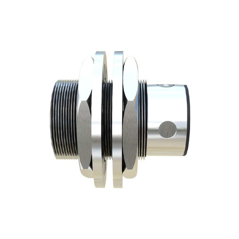
Capacitive proximity sensors, capable of detecting both metallic and non-metallic materials, use a square with two parallel lines extending from one side, often the left, into the square. These lines represent the plates of a capacitor, indicating the sensor's principle of operation based on changes in capacitance.
Ultrasonic proximity sensors use sound waves. Their symbol is a square with a distinctive "arc" or series of concentric arcs emanating from one side, resembling a sound wave or loudspeaker symbol, denoting the ultrasonic transducer.
Photoelectric sensors, or photo-eyes, have a more descriptive symbol. It consists of two main components connected by a dashed line. One component is a square or circle with two arrows pointing outward (the light emitter, often an LED). The other is a square or circle with a small triangle pointing inward (the light receiver, a phototransistor or photodiode). The dashed line between them represents the light beam. Different arrangements (through-beam, retro-reflective, diffuse) are implied by the schematic layout, not by a change in the fundamental symbols.
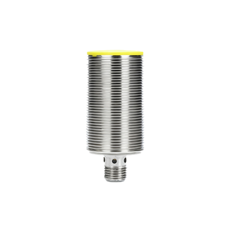
The output function of the sensor is denoted separately from the sensor type symbol. The output is represented by standard electrical switch symbols placed adjacent to or within the sensor's rectangle. A normally open (NO) contact is shown as two parallel lines that are not touching. A normally closed (NC) contact is shown as the same two parallel lines but with a diagonal line crossing through them. For a solid-state PNP (sourcing) output, a specific symbol resembling an arrow pointing outward from the switch is used. An NPN (sinking) output uses an arrow pointing inward.
A complete proximity sensor designation on a schematic integrates several elements. It includes the sensor type symbol (e.g., square with a diamond), the output switch symbol (e.g., NO contact), and a unique alphanumeric tag, such as "PRX1" or "PS01". The tag is keyed to a legend or bill of materials. Connection points are clearly marked: typically, two wires for power supply (often labeled +V or L+ and 0V or M) and one wire for the switched output signal (load). Three-wire and four-wire sensors are common, with the extra wire sometimes being a second complementary output or an analog signal line.
For example, a standard 3-wire DC inductive proximity sensor with a PNP NO output would be drawn as a square with a diamond inside. Attached to it would be the NO switch symbol with the PNP arrow. Three lines would connect: one to a +24V rail, one to the 0V rail, and the output line going to the load (like a PLC input or relay coil).
Mastering these symbols prevents costly errors during machine installation and maintenance. Misinterpreting an NC symbol for an NO, for instance, can lead to a system behaving in the exact opposite of the intended manner. Similarly, confusing a PNP and NPN symbol can result in incorrect wiring that may damage the sensor or the controller.
In conclusion, the electrical symbols for proximity sensors are not arbitrary drawings but a precise, standardized code. They concisely convey the sensor's technology (inductive, capacitive, etc.), its electrical output configuration, and its wiring requirements. Proficiency in interpreting these symbols is a fundamental skill for electrical engineers, technicians, and automation professionals, enabling them to effectively translate a two-dimensional schematic into a functioning, reliable control system.