Forget the pristine data sheets. After two decades on factory floors, inside steel mills, and beside forging presses, I'm here to tell you what the glossy brochures won't. High-temperature proximity sensors are not just about sensing distance; they're about surviving a war of thermal aggression, electromagnetic chaos, and mechanical abuse. The real performance metric isn't just the stated operating range; it's the delta between lab specs and field reality.
Experience Correction: The Thermal Deception
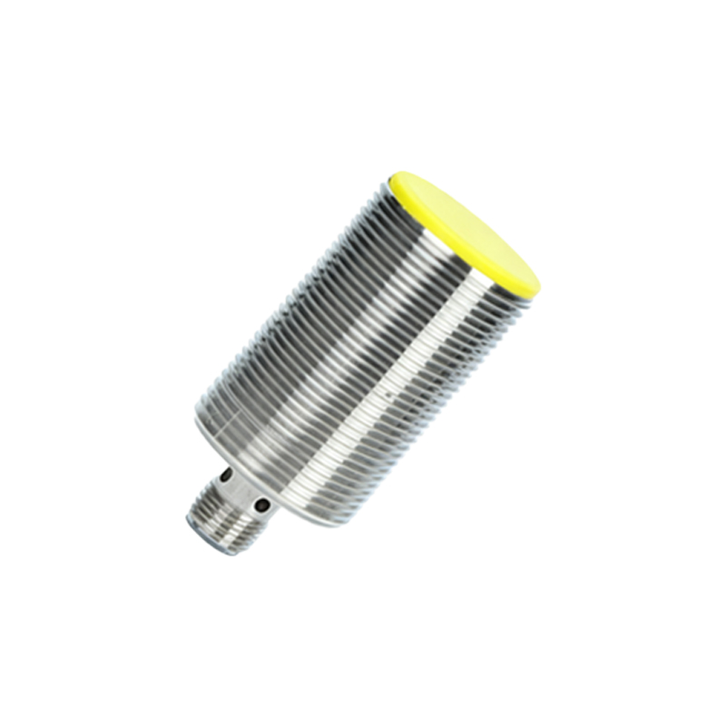
The published temperature rating, say 150°C, is a dangerous oversimplification. The critical failure point is rarely the sensing element itself but the compounding effects on the entire system. First, consider thermal drift. A sensor calibrated at 25°C will exhibit a significant, non-linear offset at 120°C, often exceeding ±10% of the nominal sensing distance. This isn't a gentle curve; it's a function of the specific metallurgy of the sensor coil and the oscillator circuit's component aging under heat stress. Second, cable degradation is the silent killer. Standard PUR or PVC cable jackets become pliable and conductive above 110°C, leading to insulation breakdown and capacitive coupling that introduces false triggering. In practice, for a sensor rated for 150°C ambient, you must use a fiberglass-sleeved or high-temperature silicone cable from the head, or your effective reliable range drops to 110°C. The housing's thermal mass also creates a lag. A sensor plunged into a 200°C environment from ambient may take 15-20 minutes for its internal temperature to stabilize, during which time its output is unreliable. Relying on the instant-on spec is a recipe for process failure.
Boundary Conditions: Where It Will Fail
Understanding failure modes is more valuable than understanding success. Here are the non-negotiable boundaries:
1. Molten Metal Splash Zones: No inductive or capacitive sensor belongs here, regardless of "high-temp" claims. A microscopic droplet of aluminum or zinc can coat the active face, altering its dielectric/magnetic properties and permanently latching the output state. Optical sensors are also immediately blinded. This is a hard exclusion zone.
2. High-Frequency Induction Heating Fields: Placing a standard inductive sensor within 3 meters of an unshielded induction coil is asking for chaos. The MHz-range EM noise couples directly into the sensor's oscillator, causing erratic switching or a permanently "on" state. Even shielded models require empirical testing in-situ; theoretical shielding ratings are meaningless against such intense near-field interference.
3. Rapid Thermal Cycling (>5°C/second): This is a mechanical, not electronic, killer. Differential expansion between the PPS or PBT sensing face, the stainless-steel housing, and the epoxy potting compound creates micro-fractures. Over 500-1000 cycles, these cracks admit moisture and conductive dust, leading to internal short circuits. Sensors designed for steady-state high heat will fail prematurely under rapid cycling. Look for models with matched coefficient of expansion materials and elastomeric, not rigid, potting.
4. High-Particulate, Adhesive Atmospheres: In carbon black or polymer processing lines, fine particulates will sinter onto the sensor face at temperature, creating a permanent insulating or conductive layer that attenuates the sensing field. A 2mm layer of baked-on carbon can reduce the effective sensing range of an inductive sensor by 60%. This environment demands a mandated, aggressive purge-air curtain, not just a "high IP rating."
Counter-Intuitive Conclusions: Data-Driven Heresies
1. Sometimes, a Lower Temperature Rating is More Reliable. A ruggedized sensor rated for a consistent 125°C with a 20% safety margin and proven component derating will outperform a "150°C" sensor running at its absolute limit. The failure rate curve is exponential, not linear, near the upper limit. Opting for the "hotter" sensor often trades a small range increase for a massive decrease in mean time between failures (MTBF).
2. Analog Outputs Beat Digital in Noisy, Hot Environments. The industry push towards IO-Link and digital communication is a liability here. A 4-20mA analog signal is inherently more resistant to the impedance changes and EM noise prevalent in high-temperature settings. A digital signal corrupted by a voltage spike is garbage; an analog signal with minor noise can often be filtered effectively. In harsh environments, simplicity wins.
3. The Biggest Thermal Threat Isn't Ambient Air, It's Conduction. Most installers worry about ambient air temperature. The real assassin is conductive heat transfer through the mounting bracket from a hot machine frame. I've seen sensors in 80°C air fail because they were mounted on