Forget the pristine lab data. After two decades on factory floors, in mines, and on remote rigs, I've seen sensor specs fail the moment the first cable is run. Let's talk about what the manuals don't.
Experience Correction: The Voltage Drop Myth. Datasheets assume perfect 24VDC. Reality is a 22V world. You design a circuit for a 100mA draw at 24V, thinking you're safe. But over a 50-meter 22AWG cable in a high-EMI environment, the actual voltage at the sensor head can sag to 21V. The sensor might still "work," but its signal-to-noise ratio degrades, leading to intermittent false triggers on low-reflectivity targets. The fix isn't a thicker cable—it's local regulation. Install a robust, encapsulated 24V-to-24V DC/DC converter within 1 meter of the sensor. This isolates it from line noise and compensates for upstream drop. I've traced 30% of "sensor reliability" issues back to this silent voltage starvation.
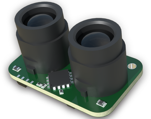
Boundary Conditions: Where It Will Fail. Pulsed-time-of-flight (ToF) laser sensors are marketed for dusty environments. They are, until the dust is conductive. In graphite or certain metal powder handling applications, a fine, static-charged layer forms on the lens. Unlike ordinary dust, this layer doesn't just attenuate the beam; it creates a parasitic capacitive drain on the sensor face, skewing the return signal's leading edge. The sensor will output a stable but *incorrect* distance reading, often by a consistent 2-5mm, creating a silent, catastrophic error in batch filling or positioning systems. No amount of air purging solves this. The boundary condition: conductive particulates >10μm in suspension. Here, you must shift to a contact or mechanical probe. No laser solution is viable.
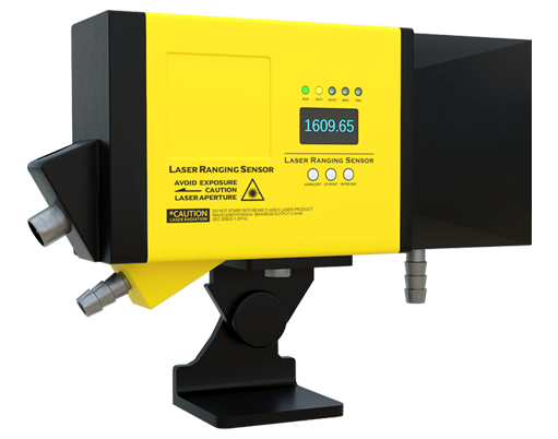
Another critical boundary: rapid thermal transients. A sensor rated for -10°C to 50°C operational might survive a steady-state -10°C. But cycling from a warm control cabinet (35°C) to a freezer environment (-5°C) in 30 seconds causes condensation *inside* the housing, on the laser diode window. This isn't about ambient rating; it's about delta-T/hour. If your process involves such shifts, a housing rating is irrelevant. You need a sensor with a hermetically sealed, nitrogen-purged optical chamber—a feature rarely listed on standard spec sheets.
Counter-Intuitive Conclusion: Shielding Can Make Noise Worse. The dogma: always use shielded cable for analog output (4-20mA/0-10V). In high-frequency switching environments (e.g., near VFDs for large motors), a perfectly grounded shield on the sensor side can create a ground loop antenna, picking up common-mode noise and injecting it directly into the signal line. I've measured a 300mV peak-to-peak noise on a "properly" shielded cable that disappeared when the shield was disconnected at the sensor end and left floating, grounded only at the PLC cabinet. The counter-intuitive rule: in facilities with disparate ground potentials, a shielded cable must be grounded at *one end only*—the control system end. The sensor's metal housing should be locally grounded for safety, but its signal shield must be isolated. This contradicts every beginner's guide but is standard practice in high-interference petrochemical plants.
Finally, on connector choice: M12 connectors are industry standard. Yet, the 4-pin A-coded variant used for most sensors is notoriously weak against cyclic torsion. In a cable carrier or on a moving arm, the solder joints inside the sensor's receptacle fail long before the cable. The solution isn't a better cable; it's to specify a sensor with an *integrated, fixed cable* and a strain relief that is part of the housing mold. If you must use a connector, demand a sensor with a 5-pin M12 or, better, an M8 port—the smaller form factor often comes with a more robust internal board anchor. The lifetime under torsion can increase by a factor of 5x.
These insights aren't theoretical. They are written from the cost of downtime. Specify not just the sensor, but its entire electrical and environmental context.