For two decades, I've watched laser sensors fail where datasheets promised success. The glossy brochures tout micron-level precision and 99.9% reliability, but reality on the factory floor, in mining pits, and on offshore rigs tells a different story. This is not a primer. This is a dispatch from the trenches.
Experience Correction: The Myth of "Stable" Performance. Theoretical specifications are derived in clean-room conditions at 20°C. In实战, a ±30°C thermal swing across a steel mill conveyor isn't an anomaly; it's Tuesday. The critical deviation isn't just in the stated ±0.05% F.S. accuracy. It's in the *thermal zero drift* and *thermal sensitivity drift*, parameters often buried in footnotes. A high-end triangulation sensor might spec a zero drift of 0.01% F.S./°C. In a 40°C delta, that's 0.4% error before it even sees a target. For a 100mm measuring range, that's a 400µm blind error, rendering micron-level repeatability irrelevant. Furthermore, airborne oil mist—ubiquitous in machining—coats the optics not uniformly, but in a gradient film, causing asymmetric signal attenuation that calibration routines cannot fully compensate for. Your "stable" output is drifting 2-3% per shift, and you'll blame the target.
Boundary Conditions: Where This Technology Breaks. Laser sensors are not universal tools. Deploy them in these scenarios at your peril:
1. Low-Density Targets: Measuring fine powders (e.g., titanium dioxide, flour) or aerated foams. The laser partially penetrates the surface, scattering within the material. The receiver detects a diffuse return from a *volume*, not a surface, leading to readings that are physically impossible (e.g., a powder bed appearing 10mm thicker than it is). Time-of-flight sensors are particularly egregious here.
2. High-Velocity, Non-Lambertian Surfaces. Measuring the wear on rapidly moving, highly polished turbine blades. The specular reflection directs the laser spot's return away from the receiver's aperture, causing dropouts. The common "fix" of increasing laser power can create localized thermal blooming on the target surface, altering the very property you're trying to measure.
3. Plasma-Rich Environments. Near high-power welding stations or plasma cutters. The ionized gas cloud absorbs and refracts the specific wavelength of the laser (commonly 650nm red or 850nm infrared), creating a fluctuating null zone. The sensor doesn't fail; it gives a perfectly stable, completely wrong reading of the plasma front, not the workpiece.
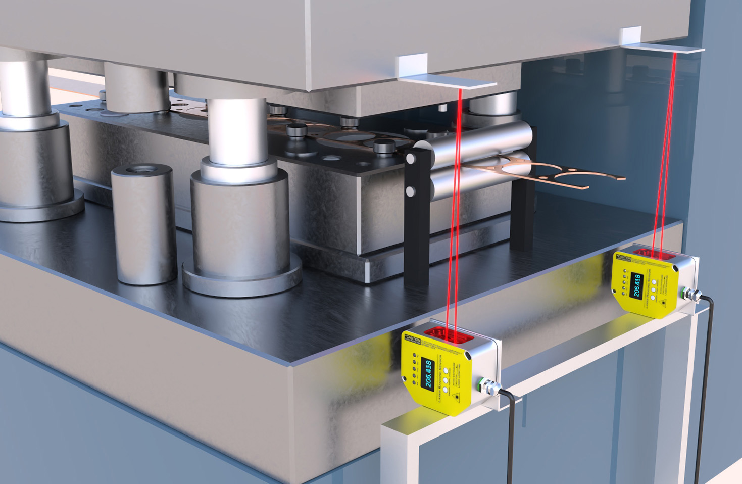
Counter-Intuitive Conclusion: Sometimes, a "Worse" Sensor is the Better Tool. The industry obsession with higher resolution and faster sampling is often misguided. Here’s the heresy: In environments with high vibrational noise (e.g., stamping presses, rock crushers), a sensor with a *slower* response time and *lower* native resolution, paired with robust analog filtering and a large, forgiving spot size, will deliver more reliable and actionable data than a cutting-edge, high-speed laser. Why? It naturally integrates out high-frequency mechanical noise that would alias into your measurement signal. You trade theoretical precision for operational integrity. The data you get is less "precise" in a lab sense but is a truer representation of the macro-state of your target. I've seen 100kHz sensors provide beautifully detailed, utterly useless graphs of vibration, while a 5kHz sensor with proper damping gave a clean trend line that predicted bearing failure a week in advance. Don't buy specs. Buy results.
The ultimate metric is not sensor accuracy, but *decision-making fidelity* over 10,000 hours of continuous punishment. Choose accordingly.