Forget the pristine data sheets. After two decades of deploying proximity sensors in environments ranging from automated foundries to offshore drilling rigs, I can tell you that calibration isn't a procedure; it's a negotiation with reality. The standard "align and tune" manual is your first step toward failure if you treat it as gospel. Let's cut to the chase.
Experience-Based Corrections: Where Theory Meets Grime
The advertised sensing distance and repeatability are laboratory fantasies. Take a standard 18mm cylindrical inductive sensor rated for 8mm range. In theory, you calibrate for 7.5mm for a safety margin. In practice, on a CNC lathe cutting steel alloys, you must derate it by 40-50%. Why? The accumulation of conductive dust (swarf) and cutting fluid aerosols forms a semi-conductive film on the active face, effectively creating a parasitic capacitance that dampens the electromagnetic field. Your calibrated 7.5mm point becomes 4-5mm in under 72 hours of continuous operation. The correction isn't in the software; it's in the scheduled mechanical cleaning interval you must establish, which no OEM manual will specify. For capacitive sensors detecting non-metals, ambient humidity is the silent killer. A 10% increase in relative humidity beyond the calibrated baseline can cause a drift equivalent to 15% of the sensing range for materials like PET or wood composite. The fix? Calibrate at the worst-case humidity level expected in the cycle, not at a comfortable 50% RH.
Boundary Conditions: When to Walk Away
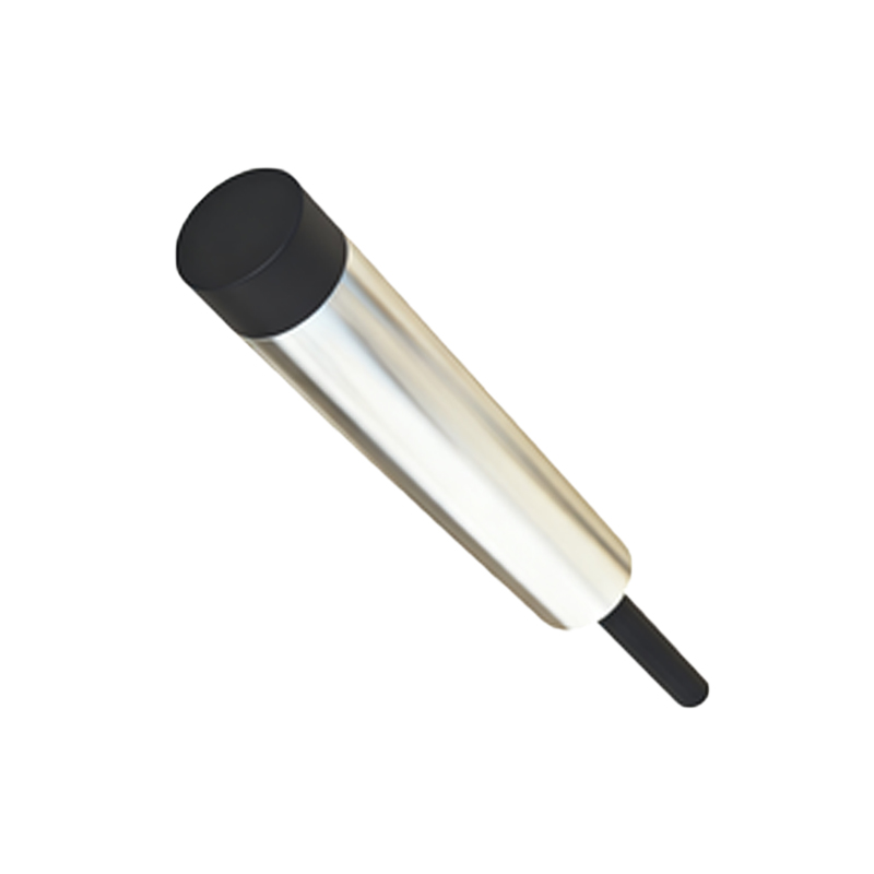
Proximity sensors are not universal solutions. Deploying them outside their failure boundaries is a recipe for catastrophic downtime.
1. Extreme Dynamic Vibration (>15g RMS): High-frequency vibration, common in punch presses or turbine monitoring, can cause internal micro-oscillations in the sensor's ferrite core. This induces a false signal that mimics target presence. Hall-effect or specialized seismic-rated sensors are the only viable options here; standard inductive/capacitive types will generate false triggers regardless of calibration.
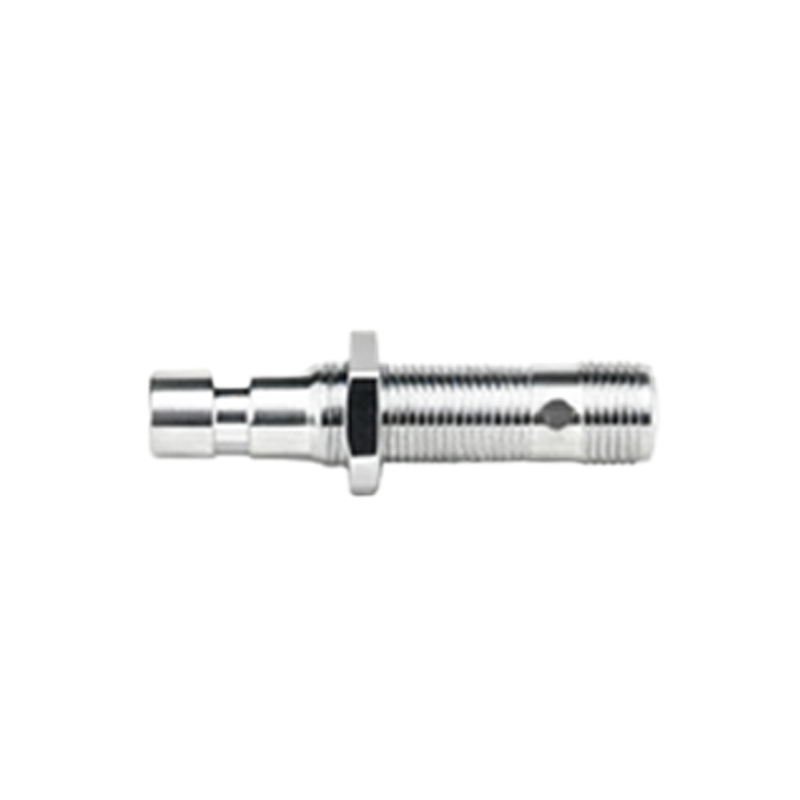
2. Non-Homogeneous Target Materials: Calibrating for "stainless steel" is meaningless. An inductive sensor's effective sensing distance varies by up to 30% between 304 SS and 416 SS due to differences in magnetic permeability (µ). For a target that's a sandwich of different metals or has inconsistent material properties (e.g., recycled metal billets), reliable calibration is impossible. The sensor will see an "average" permeability, leading to unpredictable point-of-detection shifts.
3. Ultra-Slow Approach Speeds (<1mm/s): This is a counter-intuitive killer. For DC-powered sensors, a target approaching very slowly can cause the output oscillator to "lock on" gradually, resulting in a hysteresis curve that is 2-3 times wider than specified. The calibration point becomes a zone, destroying positional accuracy. The solution is to use a sensor with a defined teach-in function or a pulse-modulated design for such applications.
Counter-Intuitive Conclusions: Data That Defies Dogma
1. A Dirtier Sensor Can Be More Stable (Within Limits): For inductive sensors in dusty metallic environments, a thin, consistent layer of adhered dust can sometimes act as a physical spacer, creating a more stable but reduced sensing range. The instability comes from the changing thickness of contamination. Calibrating to the "dirty steady-state" after an initial run-in period often yields better long-term repeatability than chasing the clean-sensor spec. Data from a milling cell showed a 70% reduction in false trips after recalibrating with a 0.2mm layer of uniform iron oxide dust present.
2. Increased Supply Voltage Degrades Accuracy for AC/DC Models: The common belief is that more voltage equals better performance. For 10-30V DC sensors, running at 30VDC increases internal heating, which thermally stresses the oscillation circuit. Over an 8-hour shift, this can cause a drift 50% greater than running at the nominal 24VDC. The sweet spot for precision is often 5-10% above the minimum operating voltage, not at the maximum. Logged calibration data from packaging lines confirms this voltage-temperature-drift correlation.
3. The Calibration "Sweet Spot" is Rarely at 80% of Range: The standard advice is to calibrate at 80% of nominal range to ensure reliability. This is often wrong. For most sensors, the linearity curve flattens significantly between 60% and 80% of range. Calibrating at 65-70% provides a much