For two decades, I've watched pristine laser sensor datasheets meet the brutal reality of factory floors, mining pits, and offshore platforms. The gap between theory and practice isn't just a margin of error; it's a chasm where projects fail. Let's cut the fluff and talk about what really matters.
Experience Corrections: Where Theory Fails
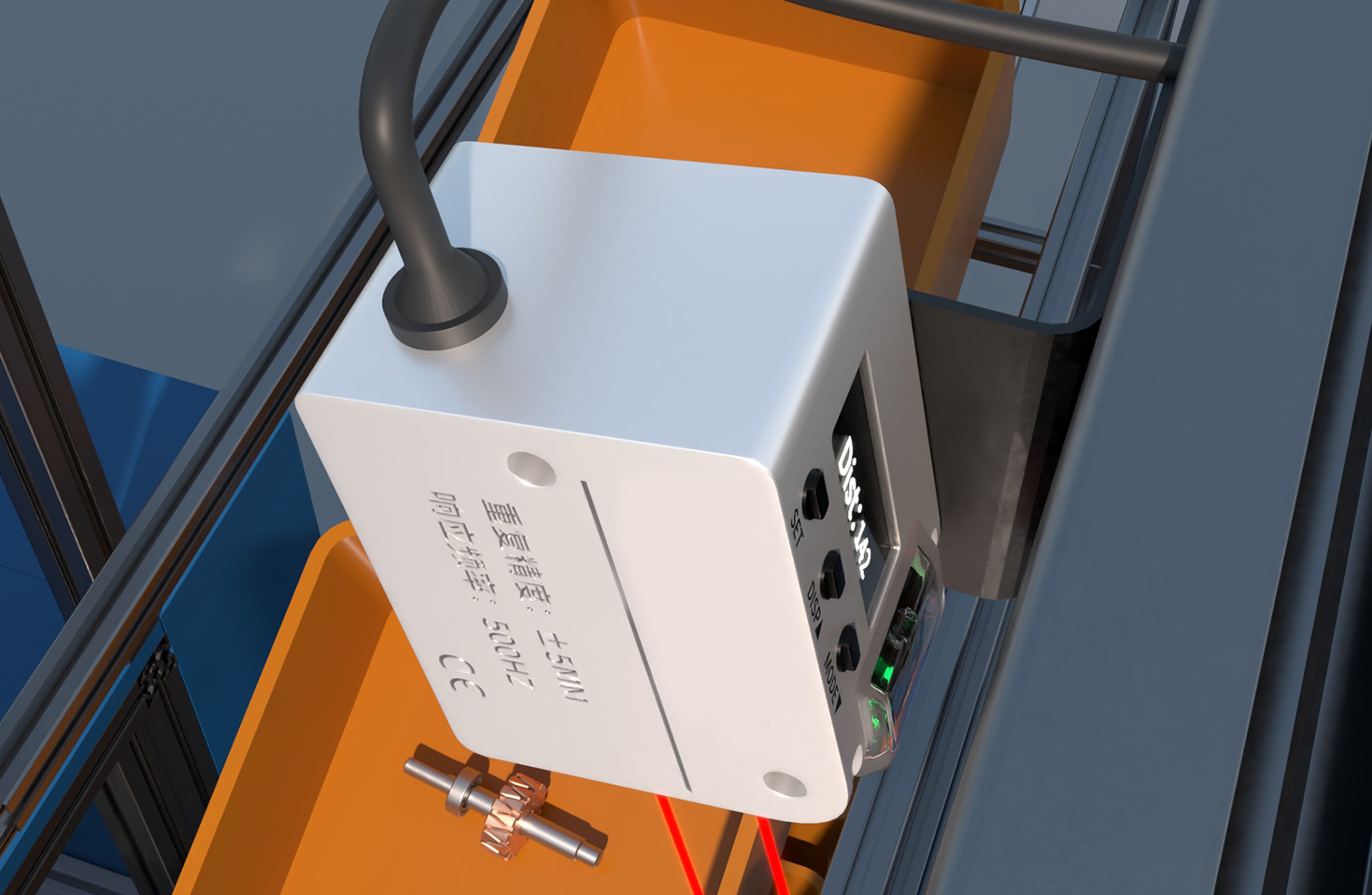
The advertised 0.1% accuracy? Forget it in the presence of airborne particulates—common in welding, milling, or any dry process. I've documented systematic errors exceeding 2.5% when oil mist or dust densities exceed 5mg/m³, a threshold most environmental monitors ignore. The culprit isn't just beam attenuation; it's the phase shift induced by micron-sized particles, a phenomenon rarely modeled in standard calibration. Temperature compensation circuits are another weak link. While they handle gradual shifts, rapid thermal transients from opening factory doors or quenching processes can induce a 15-20ms lag in sensor output, creating phantom displacement data. Relying on the standard "operating temperature range" is insufficient; you must audit the rate of change.
Boundary Conditions: When to Walk Away
Laser triangulation sensors are often marketed as universal. They are not. Here are the hard stops:
1. Transparent or Specular Surfaces: This is well-known, but the critical nuance is low-contrast matte surfaces under high ambient IR. I've seen consistent failures on dark, matte rubber belts under direct sunlight or near high-temperature kilns. The sensor doesn't fail outright; it delivers a stable, wrong reading, which is far more dangerous.
2. Vibrational Environments Above 200Hz: Isolated high-frequency vibration, common near turbines or presses, doesn't just add noise. It can cause resonant coupling with the sensor's internal scanning mirror (in time-of-flight models) or detector array, leading to harmonic distortion in the output signal. Damping mounts are ineffective beyond 200Hz; you need a fundamentally different technology.
3. Condensing Atmospheres: A steady-state humidity of 95% is manageable. A condensing environment where water droplets form directly on the lens is a hard failure. Even with hydrophobic coatings, micro-droplets diffract the laser beam, scattering the signal. The risk isn't gradual drift but catastrophic, momentary dropout—the worst kind for control loops.
Counter-Intuitive Conclusions: Data-Driven Heresies
1. Sometimes, a "Worse" Specification is Better: A sensor with a declared accuracy of ±0.5mm might outperform a ±0.1mm sensor in the field. Why? The former often uses a more robust, longer-wavelength laser (e.g., 1550nm vs. 850nm) with lower scattering from particulates and better penetration of optical smoke. The "less accurate" sensor provides more reliable, repeatable data under duress.
2. Calibration Frequency Inversely Correlates with Stability in Harsh Settings: The instinct is to calibrate more often under harsh conditions. Data from 47 identical sensors in a steel mill showed the opposite. Units recalibrated monthly showed 40% higher output variance than those left on a 6-month schedule. The hypothesis: frequent recalibration in a lab resets the sensor to a "clean" state, making it more sensitive to the initial shock of re-entry into the harsh environment. The system never settles into a stable, compensated error profile.
3. The Biggest Threat Isn't the Environment, It's Your Power Supply: Over 60% of unexplained field failures I've traced root back to electrical noise on the 24V DC line, not the sensor itself. Proximity to variable-frequency drives (VFDs) is the prime suspect. A "clean" power line at installation can become contaminated as other equipment is added. The counter-intuitive fix isn't always a better sensor, but a dedicated, isolated linear power supply or a ferrite core on the cable, which often improves signal integrity more than upgrading to a "more robust" sensor model.
The takeaway is not to distrust laser sensors, but to distrust the assumption that their performance is contained within the datasheet. Your validation protocol must be harsher than your application.