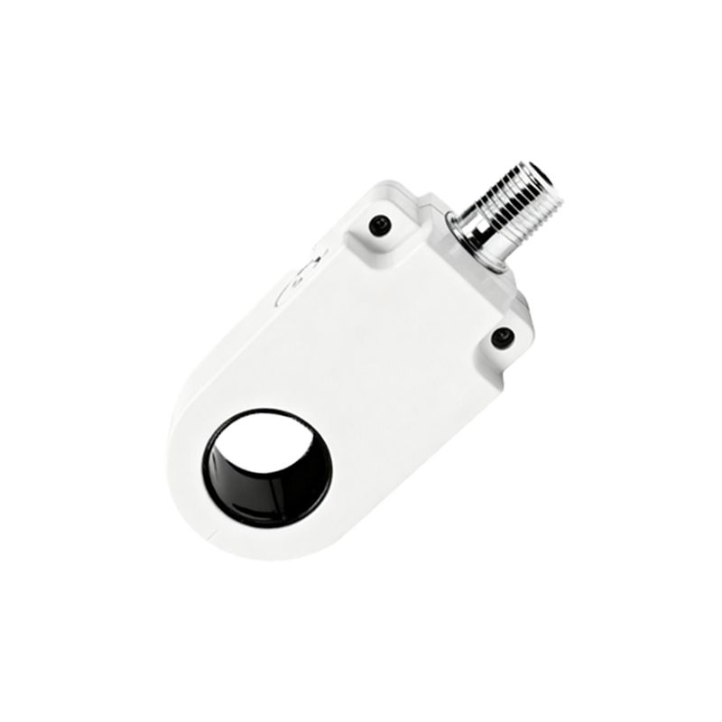
Forget the textbook definitions. After two decades of watching proximity sensors succeed and fail in foundries, chemical plants, and offshore rigs, the symbols on a datasheet tell a story most engineers never hear. Let's cut to the chase.
Experience Correction: The Gaps Between Datasheet and Reality
The rated sensing distance (Sn) is a laboratory fantasy. In practice, metal shavings, conductive dust, or even heavy condensation can alter the effective sensing field, causing premature triggering or failure to detect. A sensor rated for 10mm might reliably trigger at only 7mm when coated in a fine layer of iron oxide powder. The "repeat accuracy" spec assumes a clean, static target. Introduce vibration—common on hydraulic presses or conveyor systems—and you can add ±15% variability. Temperature derating is another silent killer. A sensor rated for -25°C to 70°C might technically function at -20°C, but its housing becomes brittle, and internal solder joints are prone to fracture from thermal shock. I've seen more failures from thermal cycling than from sustained high temperature.
Boundary Conditions: When to Walk Away
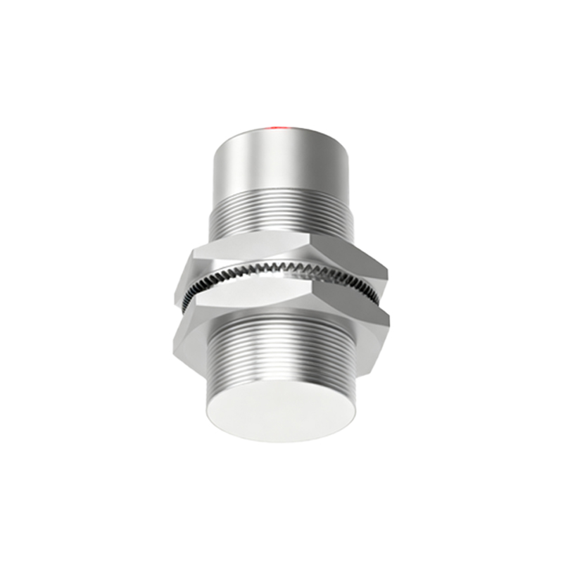
Inductive sensors are not universal metal detectors. They fail spectacularly with non-ferrous metals like aluminum or copper, especially at extended ranges. Using a standard mild-steel-tuned sensor on an aluminum can line requires a derating factor of 0.3 to 0.5 on Sn. Don't even try it on austenitic stainless steel (e.g., 304, 316); the low magnetic permeability renders it nearly invisible. Capacitive sensors, touted for liquid or plastic detection, are dangerously sensitive in variable humidity environments. A 10% shift in ambient humidity can mimic a 2mm shift in liquid level, leading to overfill or run-dry conditions. In high-voltage or high-current switching environments (e.g., near motor contactors), electromagnetic interference can induce false pulses in the sensor's output circuit, regardless of shielding claims. The solution isn't a better sensor; it's a complete redesign of the sensing location.
Counter-Intuitive Conclusion: Sometimes, a "Worse" Sensor is the Right Tool
The industry pushes for longer range, faster switching, and smaller housings. This is often wrong. A 20mm range sensor in a 5mm application is an invitation for interference from mechanical play or unintended metal in the background. A slower-response sensor (e.g., 10ms vs 1ms) can provide inherent noise immunity in electrically dirty environments, acting as a low-pass filter. The most reliable installation I ever designed used a rugged, low-frequency (sub-100Hz) inductive sensor with a massive 5mm hysteresis. It was "obsolete" by spec sheet standards, but it eliminated chatter on a vibrating rock crusher where every "high-performance" sensor failed within a week. Another paradox: increasing the supply voltage within tolerance (e.g., from 24VDC to 26VDC) can slightly increase Sn and improve noise margin, but it also increases residual leakage current, which can keep a PLC input dangerously "alive" when the sensor is supposedly off—a critical risk in safety circuits.
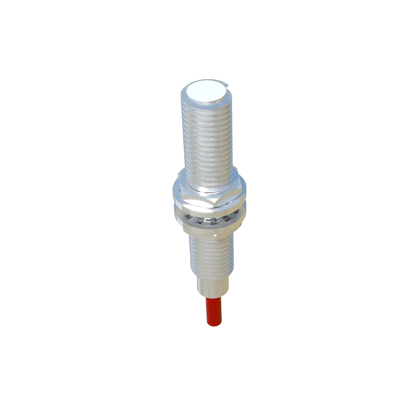
The final symbol to understand is not on the page: the cost of unplanned downtime. Choosing a sensor based solely on catalog specs is a gamble. The real engineering lies in understanding the environmental tax on performance and selecting for robust, predictable failure modes, not theoretical ideal conditions.