For two decades, I've watched proximity sensors fail in ways the glossy datasheets never predicted. The industry is saturated with theoretical specs measured in lab conditions—sensing distances, repeatability, IP ratings. Reality on the factory floor, in mining operations, or on offshore rigs tells a different story. This is not a primer. This is a dispatch from the trenches, focusing on inductive and capacitive variants where the rubber meets the road.
Experience Correction: The Gaps Between Spec and Reality
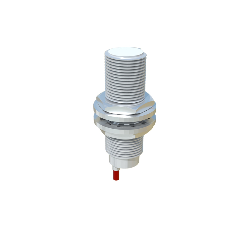
The most glaring deviation is in the stated sensing distance (Sn). Manufacturers calibrate this using a standard 1mm thick, square mild steel target. In practice, your target is rarely that. A worn, curved, or rusty gear tooth can effectively reduce Sn by 30-40%. For non-ferrous metals like aluminum, the effective sensing distance can plummet to 50% or less of the rated Sn. Temperature is another silent killer. A sensor rated for -25°C to 70°C might maintain its switching function, but its response time can degrade by up to 20% at the extremes, causing missed counts in high-speed bottling or packaging lines. Vibration, often overlooked, doesn't just cause physical damage; it can induce false triggering in poorly shielded DC sensors due to wire harness microphonics, a phenomenon rarely mentioned in manuals.
Boundary Conditions: When to Walk Away
Proximity sensors are not universal solutions. Knowing their failure zones is critical.
1. Extreme Particulate Environments: An IP67 rating means it can survive immersion, not that it can see through conductive sludge. In metal grinding or carbon dust environments, metallic particulates can adhere to the active face of inductive sensors, gradually dampening the electromagnetic field and causing a permanent, undetected drift in sensing point until failure. Capacitive sensors in flour or powder silos become utterly unreliable as material buildup constantly alters their baseline.
2. High-Speed Ferrous Swarf: In CNC lathe turrets or magnetic separator chutes, hot, stringy ferrous swarf can bridge the sensor face. This doesn't just block detection; it can create a permanent "target present" signal by forming a conductive bridge, leading to critical machine faults.
3. Sub-millimeter Precision Positioning: Do not use standard barrel sensors for precision end-of-travel detection on linear actuators expecting micron-level repeatability. Hysteresis—the difference between the switch-on and switch-off point—is a fixed physical property, often 3-10% of Sn. For an 8mm sensor, that's a 0.5mm dead zone, which is catastrophic for precision assembly.
4. Unstable Power Supplies: These sensors, especially analog-output types, are highly sensitive to ripple and noise on DC lines. Placing them on the same circuit as variable frequency drives (VFDs) or large solenoids without independent, filtered power is an invitation for erratic behavior. The risk isn't just failure; it's intermittent, diagnosis-heavy failure.
Counterintuitive Conclusions: Data-Driven Insights That Defy Common Sense
1. Sometimes, a Less Sensitive Sensor is More Robust. In environments with airborne metallic dust, selecting a sensor with a shorter rated sensing distance can improve reliability. The reduced electromagnetic field is less susceptible to influence from ambient particulates, decreasing false triggers. You trade off installation flexibility for operational stability.
2. Shielding Can Be a Detriment in Specific Setups. A shielded (flush-mountable) sensor is often chosen for mechanical protection. However, when detecting the teeth of a small, fast-rotating steel gear, an unshielded sensor provides a more defined and repeatable switching point due to its extended field shape, leading to better accuracy despite being more physically vulnerable.
3. The "Fail-Safe" Logic Trap. Many systems are wired for a "broken wire = stop" fail-safe. But consider a capacitive sensor monitoring high-purity liquid level in a pharmaceutical tank. Foaming can cause sustained, rapid on/off cycling. Over weeks, this thermal cycling from inrush current can fatigue solder joints more than continuous operation, leading to internal failure while the wiring remains intact, defeating the external fail-safe. The true failure mode wasn't mechanical wear but electrical-thermal fatigue induced by the application itself.
4. Analog Outputs Often Lie About Precision. A 4-20mA or 0-10V output suggesting micron-level position feedback is often an illusion. Non-linearity, especially at the extremes of the sensing range, and temperature drift of the output circuit can introduce errors exceeding 2% of full scale. For critical gap or thickness measurement, a calibrated laser system is the only choice; an