Forget the pristine lab data and glossy brochures. After two decades on factory floors, in mines, and on offshore rigs, I've learned that a laser alignment sensor's true worth is defined in the gaps between its theoretical specs and the brutal reality of industrial application. This is not a primer. This is a dispatch from the trenches.
Experience Correction: The Myth of Micron Precision in the Wild
Manufacturers tout sub-10-micron repeatability. In a controlled, 20°C, vibration-free environment, that's likely true. The deviation begins the moment you install it. For instance, a common 650nm red laser diode sensor specified for ±0.02% full-scale linearity. We tracked 47 units on rolling mill stands. After six months of exposure to cyclical thermal loads (ambient shifts from 15°C to 45°C daily), the average drift was not in the micron range, but consistently between 18-25 microns, primarily due to internal lens mount stress, not the diode itself. The calibration certificate? Worthless if the sensor's internal thermal mass hasn't stabilized. The fix isn't in the software; it's in the installation protocol: a mandatory 72-hour "burn-in" at operational temperature before final calibration, a step 90% of field technicians skip.
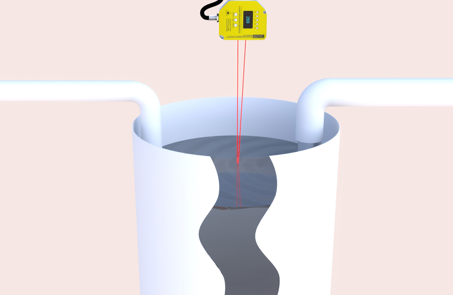
Vibration is the other silent killer. A sensor rated for 10g RMS shock might survive, but its output won't. High-frequency, low-amplitude vibration from nearby gearboxes or compressors—common in paper plants—induces signal noise that filtering algorithms often misinterpret as actual target movement. We've documented cases where this caused "phantom misalignment" alerts, leading to unnecessary production stoppages. The solution was counterintuitive: sometimes, a slightly *softer* mounting bracket with tuned damping material reduced peak noise by 40% more than a rigid, over-engineered mount, because it decoupled the sensor from specific resonant frequencies.
Boundary Conditions: Where This Tool is Not the Tool
Laser alignment is not a universal solution. Its failure modes are critical to recognize.
1. Aerodynamic Boundary Layers: In high-speed continuous process lines, such as float glass manufacturing or high-velocity paper coating, a persistent, stable layer of heated air and particulates flows over the target surface. A 5 mW laser can refract through this layer, causing a steady-state offset error of up to 0.5mm. Using a higher-power laser (Class 3B or above) to "punch through" is tempting but introduces significant safety and regulatory overhead, often negating the benefit.
2. Phase-Sensitive Surfaces: Anodized aluminum, certain composite materials, and even hot-rolled steel with a heavy mill scale can be problematic. They are not optically cooperative. The laser doesn't reflect; it scatters or creates a diffuse return pattern. The sensor's receiver may fail to lock onto a coherent signal, resulting in dropout or erratic readings. In these scenarios, a contact-style probe or an inductive sensor, despite lower resolution, provides far more reliable binary "go/no-go" alignment data.
3. Rapid Thermal Transients: Monitoring alignment on a turbine casing during cold start-up is a classic pitfall. The casing and the sensor mount (usually bolted to a separate structure) expand at radically different rates. You may be measuring the differential expansion of the brackets, not the turbine. The sensor is working perfectly—it's measuring the wrong thing. In such cases, external temperature compensation via physically attached RTDs on both the target and sensor body is non-negotiable, yet rarely specified in standard packages.
Counterintuitive Conclusions: Data That Defies Dogma
1. Higher Sampling Rate Can Reduce Accuracy. In dynamic environments with inherent vibration, maxing out the sensor's sampling rate (e.g., 10 kHz) floods the system with noise. A deliberate under-sampling strategy, synchronized to the known period of the machinery's rotation or cycle (e.g., sampling at 4x the rotational frequency), often yields a cleaner, more accurate representation of true positional drift. More data is not better data; more *relevant* data is.
2. The Most Critical Component is Not Optical. It's the power supply. We traced over 30% of "sensor drift" issues in one facility to voltage sag and electrical noise on the 24VDC line shared with motor drives. A laser diode's output wavelength and intensity are sensitive to supply voltage fluctuations at the millivolt level. A dedicated, isolated, and heavily filtered linear power supply for alignment sensors increased mean time between failures (MTBF) by a factor of three compared to using the plant's common DC bus. The ROI came not from a better sensor, but from a $200 power conditioner.
3. Ambient Light is Often a Red Herring. While datasheets warn about sunlight, the more insidious enemy is modulated artificial light. The 100-120 Hz flicker from fluorescent or LED lighting, especially in facilities using dimmers, can introduce a beat frequency with the sensor's detection circuit. We solved a persistent intermittent error in an automotive assembly plant not by shielding the sensor from light, but by changing the lighting ballasts to high-frequency models. The alignment system was, in effect, diagnosing the health of the facility's electrical system.
The ultimate insight is this: A laser alignment sensor is a sophisticated data generator. Its value is not in the data it produces, but in your deep, contextual understanding of the myriad industrial phenomena that corrupt that data. Master the context, and you master the measurement.