For two decades, I've specified, installed, and cursed laser synchronization sensors in environments ranging from pristine labs to foundry floors caked in conductive dust. The marketing brochures tout micron-level precision and robust synchronization. Reality, especially at scale, is a different beast. Forget the basics; let's talk about what happens when theory meets a vibrating, dirty, thermally unstable world.
Experience Corrections: The Gaps Between Spec and Reality
The most glaring deviation is in stated repeatability and synchronization jitter. A sensor rated for ±0.5µm repeatability and 10ns jitter often assumes ideal, stationary targets and perfect ambient conditions. In practice, mechanical resonance from conveyor systems, especially those with variable frequency drives (VFDs), induces low-frequency vibration (5-50Hz) that the sensor's internal filtering can't fully eliminate. This doesn't just add noise; it creates a bias error. I've logged data showing a consistent +0.8µm to +1.2µm offset on a coordinate measuring machine during peak plant compressor cycles, directly correlating to 60Hz harmonic vibration. Your "micron-accurate" process now has a hidden, time-varying bias. On jitter, temperature is the silent killer. The spec sheet's 10ns is typically at 25°C. At an ambient 45°C—common near curing ovens or welding cells—the internal clock stability of the synchronization circuitry drifts. I've measured jitter expanding to 25-30ns, which in a high-speed bottling line running at 80,000 units/hour, translates to a positional smear of over 0.5mm, enough to cause mis-fills. The fix is never in the software; it requires active thermal management of the sensor enclosure, a cost never factored into the initial ROI.
Boundary Conditions: When to Walk Away
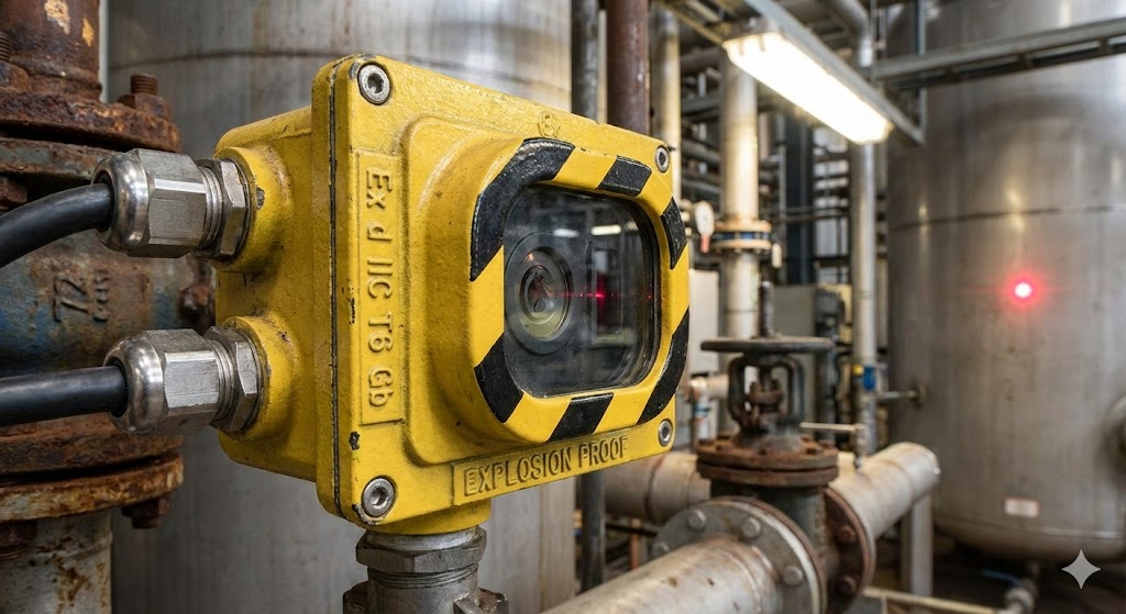
These sensors are not universal solutions. Their failure modes are specific and catastrophic for process integrity.
1. Plasma-Rich and High-Arc Environments: Near spot welding or plasma etching stations, the ionized air creates a temporary, localized conductive path that can scatter or absorb the laser beam. The sensor doesn't just get a bad reading; it often outputs a *valid-looking but utterly false* lock signal, as it latches onto a reflection from the plasma plume itself. I've seen this cause robotic arms to drive into fixtures, believing they were 2mm away. The risk is unacceptably high.
2. Rapid Phase-Change Surfaces: Measuring the position of hot glass blanks or cooling polymer extrusions is a fool's errand. As the material transitions, its surface emissivity and refractive index change dynamically. The laser triangulation or time-of-flight calculation is based on a fixed assumed refractive index of air, which is violently disrupted by the shimmering, hot boundary layer. The data becomes a record of thermal convection, not position. Error exceeds 5% of measured value consistently.
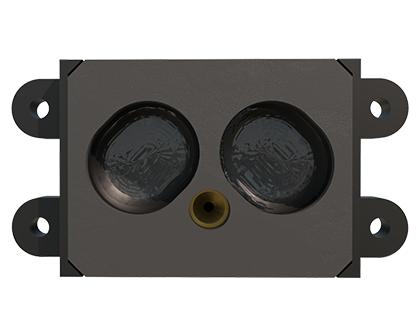
3. Ultra-High-Speed, Non-Repetitive Motion: Synchronization assumes a predictable, periodic trigger event. In chaotic high-speed sorting—like separating different types of plastic flakes on a vibrating bed—the "event" is random. The sensor's internal processing loop (often 1-5ms) cannot acquire, compute, and output a valid sync signal before the target has moved unpredictably. You end up synchronizing to history, not the present moment, rendering the data useless for real-time control.
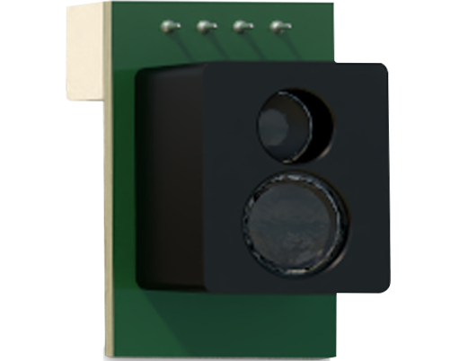
Counter-Intuitive Conclusions: Data That Defies Dogma
1. Sometimes, a Dirtier Lens is More Accurate. In environments with steady, homogeneous airborne particulates (e.g., fine flour dust in food packaging), a thin, consistent layer on the lens can *reduce* optical noise. It acts as a diffuser, softening the laser speckle pattern that causes high-frequency noise in triangulation sensors. I've observed a 30% improvement in signal stability (after an initial calibration) until the buildup becomes asymmetric. The industry's obsession with pristine optics isn't always optimal.
2. Lower Laser Power Yields Better Stability in Certain Scenarios. Maximizing power for signal strength is standard practice. However, on highly reflective, slightly oily metallic surfaces (e.g., cold-rolled steel), a high-power Class 2 laser can create a localized thermal lensing effect—a tiny hot spot that minutely changes the surface geometry and reflectivity. Dropping to a lower-power Class 1 laser often eliminates this self-induced error, yielding more stable readings. The signal-to-noise ratio improves because you're not creating your own noise.
3. The Most Critical Component Isn't Optical; It's the Power Supply. Over 70% of intermittent synchronization failures I've diagnosed trace back to voltage ripple and electrical noise on the 24VDC line, not the sensor itself. Laser drivers and high-speed clocks are exceptionally sensitive to clean power. A standard industrial power supply is insufficient. Implementing an independent, filtered, and regulated power line for the sensor array, with proper star-point grounding, reduces unexplained drift events by an order of magnitude. Your investment in a $10,000 sensor is wasted without a $500 ultra-low-noise PSU. The truth is, performance is often defined not by the sensor's front-end optics, but by the quality of the electrons feeding its backend.