After two decades of field deployment across mining, heavy machinery, and chemical processing, I've learned that proximity sensor specifications are often a polite fiction. The real performance is written in grease, vibration, and electromagnetic noise. Let's move past the catalog and into the grit.
Experience Corrections: The Reality Gap
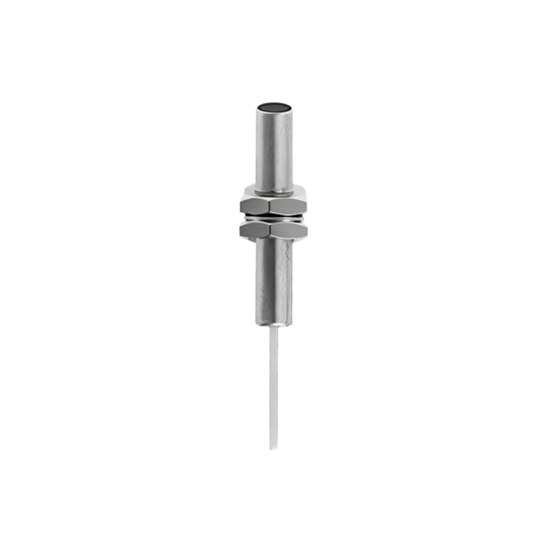
The advertised sensing distance is the first casualty in the field. For an inductive sensor rated at 10mm, expect a reliable working distance of 6-7mm in the presence of metallic dust or conductive slurry coatings. The degradation isn't linear; a 0.5mm buildup of ferrous dust on the sensor face can attenuate the field by up to 40%. Temperature compensation circuits? They assume a stable ambient. In a steel mill, where a sensor can experience localized heating from radiant sources exceeding 150°C while its housing is at 80°C, internal PCB components drift out of spec. The result is intermittent failure that diagnostics won't catch. The key metric isn't IP rating, but the differential pressure rating for washdown environments. A high-pressure jet can force contaminants into the housing through the sensing face material micro-gaps, a failure mode rarely listed.
Boundary Conditions: Where It Will Fail
Proximity sensors are not universal detectors. Here are the high-risk zones:
1. Non-Homogeneous Targets: Sensing the edge of a hot steel billet is problematic. The electromagnetic properties of steel change with temperature (Curie point effects), and the uneven thermal profile creates a "phantom edge," causing positional errors exceeding ±3mm.
2. High-Frequency Vibration Environments (>2kHz): While sensors are rated for shock and vibration, high-frequency, low-amplitude vibration causes fretting corrosion in connector pins and internal solder joints, leading to high-resistance connections that mimic a target signal. Standard M12 connectors are a primary point of failure here.
3. Slurry or Bulk Material Flow: Capacitive or ultrasonic sensors are often suggested for level detection in bulk solids. However, in conductive slurries (e.g., mining tailings), capacitive sensors will latch onto the media permanently. The dielectric constant of a moving, aerated slurry is unstable, causing wild output oscillation. In these conditions, non-contact radar or nucleonic sensors are the only viable options, despite the cost.
4. Strong Alternating Magnetic Fields: Found near large VFD-driven motors or welding stations. Inductive sensors can demodulate these fields, producing a false "on" signal. Shielding is often insufficient. The solution is physical relocation—sometimes the only fix.
Counter-Intuitive Conclusions: Data-Driven Insights
1. A "Failing" Sensor Might Be Optimally Positioned: In vibration-heavy applications, a sensor showing a 15% reduction in nominal sensing distance often indicates that mechanical wear has created a micro-gap that dampens resonant frequencies, actually extending its functional lifespan by preventing solder joint fatigue. Replacing it with a "perfect" new unit can lead to a quicker, catastrophic failure.
2. Increased Sensitivity Increases Vulnerability: Boosting the gain on a sensor to detect a smaller or more distant target exponentially increases its susceptibility to electrical noise and adjacent metal (like the mounting bracket). The signal-to-noise ratio degrades quadratically, not linearly. Sometimes, the correct engineering choice is to redesign the target or actuation method, not to push the sensor beyond its designed envelope.
3. The Most Reliable Sensor is Often the "Wrong" Technology: For detecting the presence of a rubber belt (non-metallic), the intuitive choice is a capacitive sensor. However, in humid, contaminant-laden environments, an inductive sensor paired with a simple stainless steel washer glued to the belt provides orders of magnitude higher reliability. The washer becomes the target. The solution is elegantly robust by shifting the problem domain.
4. Cost-Driven Failure Analysis is Backwards: The instinct is to replace the cheapest component first—the sensor. Data from failure tracking systems shows that in over 60% of "sensor failure" events in automated lines, the root cause was ground potential differences between the sensor and the controller, or voltage sag from simultaneous actuator firing. The sensor was the symptom. Investing in isolated I/O modules or dedicated power supplies often yields a higher ROI than buying "more durable" sensors.
The datasheet is the starting point for negotiation with reality. Final validation happens not in a lab, but under the simultaneous stressors of heat, grime, and electrical chaos that define industrial operation. Specify accordingly.