For two decades, I've watched laser line sensors transition from lab curiosities to shop-floor staples. The glossy spec sheets promise micron-level repeatability and robust performance. Reality, on a vibrating milling machine at 3 AM or in a warehouse with inconsistent ambient light, tells a different story. Forget the marketing poetry. Let's talk about the grit.
Experience Correction: The Gaps Between Datasheet and Dirt
The advertised accuracy of ±0.05% of measurement range is a clean-room fantasy. In practice, thermal drift is your primary adversary. A sensor calibrated at 22°C will introduce a systematic error of 0.01-0.02% per °C shift in the housing temperature, not the ambient air. On a steel frame machine undergoing warm-up cycles, this can mean a 50-micron drift in the first hour, completely unbeknownst to the operator relying on static calibration. The second major correction concerns surface dependency. The standard "white matte surface" calibration is a gross oversimplification. On dark, anodized aluminum, signal-to-noise ratio can drop by 60%, forcing higher laser power and accelerating diode aging. On transparent or semi-gloss surfaces, the centroid calculation of the laser line profile becomes unstable, causing jitter that exceeds nominal precision by an order of magnitude. Relying on factory specs without in-situ characterization under your specific target conditions is the first step toward failure.
Boundary Conditions: When to Walk Away
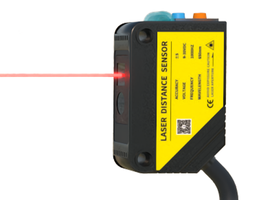
Laser line sensors are not universal tools. Deploying them outside their physical boundaries guarantees costly errors. First, high-speed dynamic measurement on vibrating platforms. If the vibration frequency (e.g., from a reciprocating mechanism) exceeds 1/3 of the sensor's profile acquisition rate, the captured line is geometrically distorted, rendering 3D reconstruction useless. Second, environments with particulate interference. Welding smoke, coolant mist, or even airborne dust will scatter the laser line. While some algorithms claim compensation, any occlusion exceeding 30% of the line's length leads to catastrophic interpolation errors. Do not use them for in-process welding inspection. Third, applications involving highly specular or mirror-like surfaces. The triangulation principle fails as the reflected beam does not return to the receiver; you'll get dropouts or phantom data points. Attempting to solve this with diffuser films often alters the measurement geometry itself. Finally, forget long-range outdoor use. Sunlight's infrared component saturates the CMOS, and thermal expansion of the housing from direct sun exposure will warp your calibration.
Counter-Intuitive Conclusion: Sometimes Slower and Dumber is Better
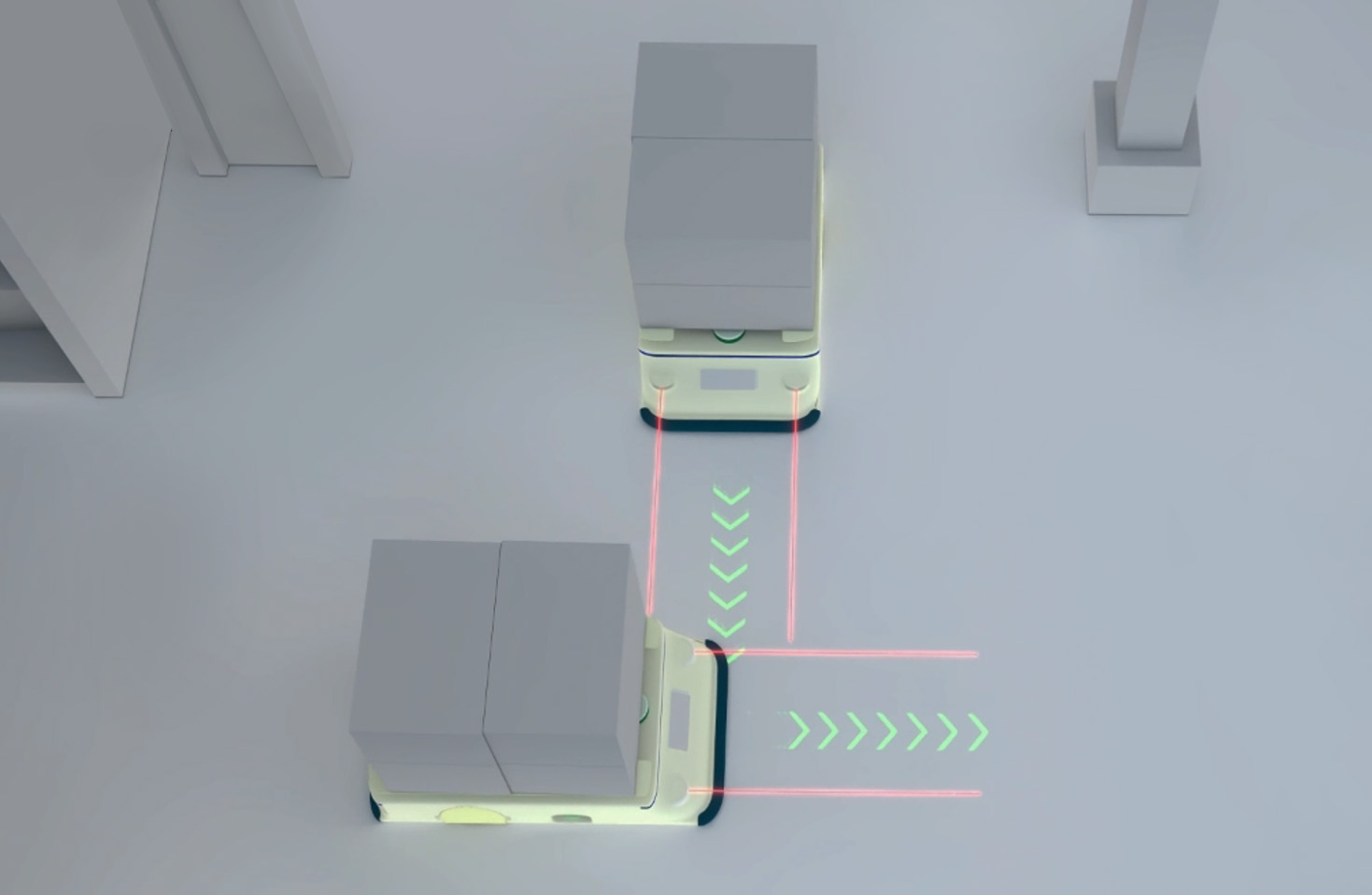
Here’s the insight that clashes with the "faster, higher resolution" mantra: For robust industrial gauging, reducing the laser line resolution and slowing the scan rate often yields superior real-world accuracy. Why? Higher resolution (e.g., 2048 points per profile) increases the data load and processing latency, forcing tighter exposure times. This makes the system more susceptible to transient environmental noise—a passing shadow, a flickering light. Dropping to 512 points allows for longer exposure integration, averaging out noise, and provides more computational headroom for advanced filtering algorithms in real-time. In one case, reducing the acquisition rate from 5 kHz to 2 kHz on a bottle inspection line decreased false rejects by 40% because the algorithm could now perform a full spatial-temporal consistency check between frames. The pursuit of peak theoretical performance often undermines systemic stability. The optimal sensor is rarely the one with the highest specs on paper; it's the one whose limitations are best understood and whose operating envelope is deliberately constrained to a well-defined, noise-resistant zone. Your goal isn't to test the sensor's limits, but to ensure it never has to operate near them.