Forget the pristine datasheets and lab-bench demos. The real performance of a proximity sensor coil isn't dictated by its nominal inductance or Q-factor. It's a brutal negotiation with the physical world, and most theoretical models fail spectacularly under fire. Here’s the unvarnished truth from two decades of deploying these components in environments ranging from automated foundries to offshore drilling rigs.
Experience Correction: The Thermal Deception and Material Drift
The textbook tells you to focus on coil geometry and excitation frequency. In reality, the dominant failure mode in sustained operation is thermal drift of the ferrite core, not the coil itself. A standard Mn-Zn ferrite core’s permeability can shift by 15-20% between 25°C and its Curie temperature, which itself is often poorly specified for transient thermal spikes. I've seen systems with a 12mm nominal sensing distance degrade to 8mm after 45 minutes of continuous cycling in a plastic injection molding machine, not due to coil damage, but because the core material entered a region of non-linear permeability. The fix? Insist on cores rated with a flat permeability-temperature curve up to at least 125°C, and never trust the "standard grade." Furthermore, the ubiquitous "IP67" rating is a trap for inductive sensors. While it protects against liquid ingress, it does nothing to prevent conductive dust accumulation (e.g., graphite, metal fines) from forming a parasitic shorted turn on the coil face, gradually damping the oscillation and reducing sensitivity. I specify an additional conformal coating on the coil face for any environment with conductive particulates, a step zero datasheets mention.
Boundary Conditions: Where It Will Inevitably Fail
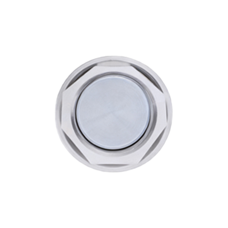
Proximity coils are not universal detectors. Deploying them outside these strict boundaries is an invitation for catastrophic failure.
1. High-Speed Ferrous Targets in Repetitive Motion: This is the silent killer. When a mild steel target approaches and retracts at frequencies above 500 Hz, the hysteresis losses within the target material itself generate significant heat. I have measured target surface temperatures exceeding 150°C. This not only poses a safety risk but creates a time-varying magnetic property in the target, leading to signal drift. For high-speed applications, you must calculate target thermal rise, not just electrical response.
2. Non-Homogeneous or Layered Targets: Attempting to sense through a painted surface or detect a stainless steel grade (like 304 vs. 316) with consistent precision is a fantasy. A 50-micron layer of nickel plating on a brass component can change the effective sensing distance by up to 30% compared to unplated brass. The sensor sees the electromagnetic properties of the surface layer first. In material sorting applications, this is a fundamental limiter, not a calibration issue.
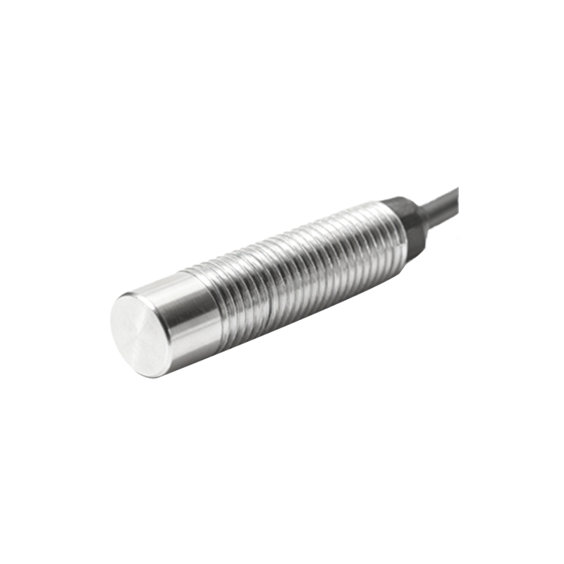
3. Extreme Dynamic EMI Environments: Near large variable-frequency drives (VFDs) or arc welders, the common-mode noise isn't just in the wiring; it's directly induced into the coil structure. Shielding is often ineffective at frequencies below 1 MHz where this noise dominates. The only reliable solution is physical separation—a minimum of 1.5 meters from VFD power cables is a hard rule—and the use of a differential, twisted-pair lead-in cable from the coil head, even if the sensor electronics are single-ended.
Counter-Intuitive Conclusion: A Weaker Field Can Be More Robust
The industry obsession with maximizing sensing distance and field strength is misguided for critical applications. My most reliable installations for detecting high-precision tool wear or small actuator positions often use under-driven coils. By operating the coil at 70-80% of its resonant peak current, you sacrifice 10-15% of the maximum possible sensing range. In return, you gain a massively improved signal-to-noise ratio (SNR) and immunity to adjacent metal. The coil's active region becomes more tightly coupled to its immediate face, making it less susceptible to disturbances from the mounting nut, housing, or background metal. The output curve (distance vs. signal) also becomes more linear in the critical first 50% of its range. This flies in the face of standard application notes that push for maximum gain. Data from a CNC tool-break detection system showed a 400% improvement in mean time between false alarms by deliberately de-tuning the coil oscillator circuit. Sometimes, the key to robustness is not pushing harder, but pulling back.
The bottom line: A proximity coil is a system interface, not a standalone component. Its performance is an emergent property of its interaction with the target material, environmental stressors, and your own drive electronics. Spec it for its failure modes, not its