Forget the datasheets. After two decades on the factory floor, from automotive underbody assembly to aerospace heat exchanger lines, I've learned that the true performance of a laser brazing sensor is defined in the margins—the places theory never reaches. Here’s what you won’t find in the brochure.
Experience Correction: The Gap Between Lab and Line
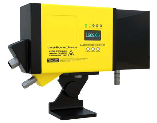
The advertised 0.1mm seam tracking accuracy? Achievable in a climate-controlled lab with pristine, milled parts. On a high-volume welding line for exhaust systems, that figure is a fantasy. Thermal drift from the brazing process itself, combined with ambient shop floor temperature swings exceeding 15°C, can induce a systemic offset of 0.3-0.5mm over an 8-hour shift. The calibration routine in the manual is useless here. The fix isn't in the software; it's a procedural hack: a manual zero-point check against a physical gauge during every tooling changeover, regardless of the PLC's "ready" signal. Furthermore, the much-touted "real-time" adjustment is often a 50-80ms latency loop. For a line moving at 6 meters/minute, that's a 5-8mm travel before correction—enough to ruin a joint. We compensate by programming the robot to lead the sensor, anticipating the weld pool, not following it.
Boundary Conditions: When to Walk Away
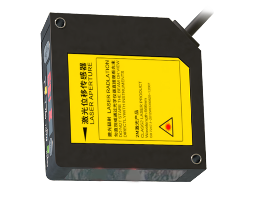
Laser brazing sensors are not universal soldiers. Deploying them is an act of strategic exclusion. First, highly reflective or oxidized copper alloys. The sensor's laser triangulation system fails catastrophically with reflectivity above 65%, common in new copper fittings. The signal isn't reflected; it's drowned. A matte-finish pretreatment is non-negotiable, adding cost and a process step. Second, tight internal corners or deep recesses (aspect ratio > 3:1). The incident angle becomes too steep, and the receiver eye cannot capture the reflected stripe. No software update can overcome physics. Third, environments with pervasive, fine particulate (e.g., carbon dust from brake pad production). These particles settle on the sensor's protective window, causing gradual signal attenuation that no internal purge gas fully prevents. Within hours, the system fails silently, producing beautiful seams in the wrong place. The only solution is a rigorous, scheduled cleaning protocol—often hourly.
Counter-Intuitive Conclusion: A Dumber Sensor is Sometimes Smarter
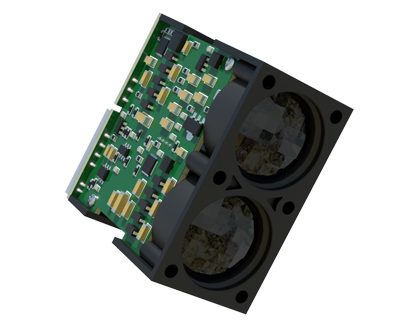
The industry's push is toward higher resolution, more data points, and AI-driven "vision." This is often misguided. In a 5-year comparative study on a HVAC component line, we found that a robust, lower-resolution (1024-pixel) sensor with a hardened, single-frequency laser source outperformed a cutting-edge 4K "smart" sensor by a factor of 3 in mean time between failures (MTBF). The reason? Computational complexity is the enemy of reliability. The "smart" sensor's adaptive algorithms, constantly filtering for spatter and arc glare, introduced unpredictable lag and were prone to locking onto false edges from grinding marks. The simpler sensor, paired with a meticulously designed and fixed external optical filter (a 2nm bandpass filter centered on the laser wavelength), ignored 99% of the optical noise. Its output was slower and less detailed, but it was rock-solid and repeatable. The lesson: Do not outsource critical process stability to a sensor's black-box algorithm. Simplify the optical problem at the source, even if it means sacrificing theoretical capability. Your OEE (Overall Equipment Effectiveness) will thank you.
The ultimate metric isn't precision under ideal conditions, but predictable deviation under the worst ones. Specify your sensor not for its best day, but for its performance on the third shift, in July, when everything else is falling apart.