Forget the pristine lab data on the datasheet. After two decades deploying red laser sensors in steel mills, chemical plants, and mining operations, I can tell you the published specs are often a polite fiction. The real performance is defined by the edge cases and failures you won't find in the marketing brochure. Let's cut to the chase.
Experience Correction: The Dust and Vibration Deception
Theoretical Parameter: A standard 650nm red laser sensor boasts a 10-meter range with a stated repeatability of ±0.1mm. The datasheet shows clean, crisp response curves.
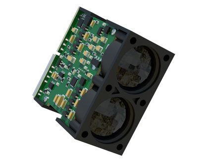
Real-World Deviation: In a cement packing plant, that same sensor's effective range collapses to under 4 meters within two weeks. Why? It's not the laser diode failing. A fine, alkaline cement dust layer, invisible to the eye, accumulates on the receiver lens. This layer doesn't just attenuate the signal; it creates a diffuse scattering effect, causing the received spot to bloom. The sensor's internal logic interprets this larger, dimmer spot as a more distant object. Your ±0.1mm precision is now a ±5mm nightmare. The fix isn't in the optics; it's in maintenance scheduling. A validated, compressed air purge cycle every 36 hours is non-negotiable, a protocol you derive from failure, not from the manual.
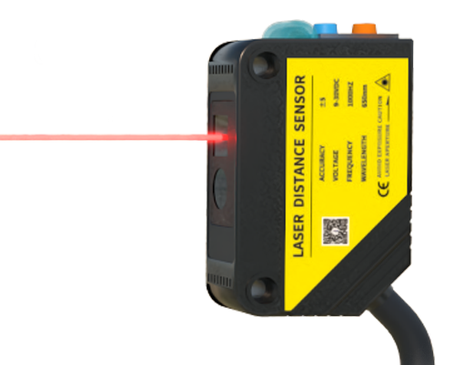
Similarly, the vibration immunity rating (say, 10-55 Hz at 2G) is meaningless if not defined in context. A sensor on a vibrating conveyor frame might survive the frequency, but the constant micro-shifts in alignment between emitter and receiver will induce a signal-to-noise ratio drop of up to 40%. This manifests not as a total failure, but as intermittent "ghost" detections. The solution is a mechanical one: mount both emitter and receiver on a single, rigid, shared bracket attached to the moving structure, not to two separate fixed points. You defeat vibration by moving with it, not resisting it.
Boundary Conditions: Where It Will Fail
Red laser sensors are not universal tools. Deploying them in these scenarios is a recipe for downtime.
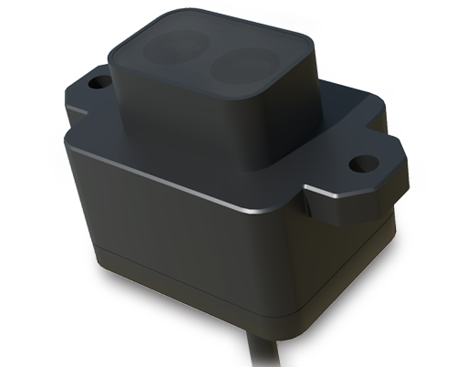
1. High-Ambient Infrared (IR) Environments: A red laser operates at 650nm, but the silicon-based photodetector inside is broadly sensitive from about 400nm to 1100nm. In a glass tempering furnace area, the background IR radiation from hot surfaces saturates the detector. The sensor becomes blind to its own modulated laser signal. Using a sensor with a narrow-band optical filter is mandatory here, yet this critical accessory is often an overlooked, costly add-on.
2. Wet, Condensing Surfaces on Dark Targets: This is a perfect storm. A black rubber belt (low reflectivity) is challenging enough. Add a film of water from condensation, and you have a specular (mirror-like) surface. The 650nm laser beam will reflect off at an angle, not back to the receiver. The sensor reads "no object" despite the belt being present. Switching to a diffuse-mode sensor or altering the installation angle to exploit the specular reflection are the only solutions.
3. Rapidly Changing Backgrounds: Detecting a transparent bottle on a high-speed conveyor is a classic pitfall. If the conveyor bed is a light gray and the gaps are dark, the sensor sees a wildly fluctuating background light level as the bottle passes. The contrast between the bottle and the immediate background behind it is too low for reliable triggering. A polarized red laser sensor, which rejects unpolarized ambient light, is the only viable option, increasing unit cost by 300%.
Counterintuitive Conclusion: Sometimes, a Weaker Laser is Better
The industry dogma is "more power, more range, more better." This is wrong in confined, reflective spaces. In a polished stainless-steel silo measuring powder level, a high-power 5mW red laser will create a disaster of multipath reflections. The beam bounces off the walls, creating multiple phantom return signals that confuse the time-of-flight or triangulation circuitry. The result is a wildly inaccurate, jittery reading. The counterintuitive but proven solution is to deliberately use a *lower-power* laser diode (1mW or less) and pair it with a timed, synchronous detection circuit. The lower power minimizes secondary reflections, and the synchronous detection locks onto only the primary return signal's timing. You sacrifice theoretical maximum range for rock-solid reliability in the specific 2-meter range you need. The data shows a 90% reduction in measurement variance using this "underpowered" setup in such environments. The takeaway: brute force optical power is often the enemy of signal clarity in real-world enclosures.