For two decades, I've specified, integrated, and cursed proximity sensors in environments ranging from automotive paint shops to deep-sea manipulators. The glossy datasheet is a starting point, but survival depends on understanding the brutal reality beyond the controlled lab. Forget the basics; here's the unvarnished truth.
Experience Correction: The Gaps Between Theory and Grime
The advertised sensing distance is a fantasy in the real world. A sensor rated for 10mm will reliably achieve perhaps 8mm on a clean, standardized target. Introduce variable surface finishes, and all bets are off. A matte black rubber conveyor roller might reduce effective range by 40% compared to the shiny mild steel test plate. Temperature isn't just about operational range; a sensor calibrated at 25°C can drift by 0.5% per 10°C change in ambient temperature. In a foundry with 60°C ambient swings, that's a 3% sensing error—enough to cause a mis-timed stamp or a crash. The "repeatability" spec? It assumes perfect mounting and zero vibration. On a high-speed packaging line, harmonic vibration at 120Hz can induce a signal noise floor that degrades actual repeatability by an order of magnitude. You don't need a failure; you get inconsistent triggering that engineers waste weeks chasing.
Boundary Conditions: When to Walk Away
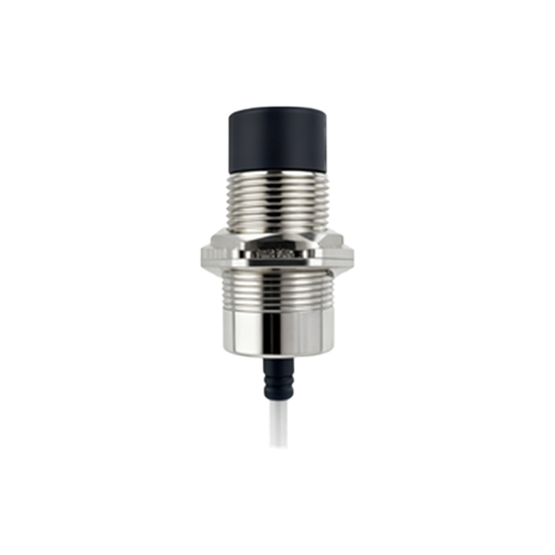
Inductive sensors are useless on non-metallics, but the critical failure is assuming all metals are equal. High-frequency oscillation inductive sensors are notoriously unreliable on austenitic stainless steels (e.g., 304, 316). Their low permeability can slash sensing distance by 60-70%, leading to intermittent failures that are misdiagnosed as electrical noise. Capacitive sensors promised a solution for non-metallics, but they are a liability in environments with variable humidity or material coatings. A capacitive sensor tuned to detect a full bottle of liquid will false-trigger on condensation or a thin, inconsistent film of oil mist. In dusty or chip-laden environments like CNC machining, any non-self-cleaning sensor face will accumulate debris, gradually shifting the sensing field. The eventual failure isn't sudden; it's a slow, insidious drift that corrupts process data long before an alarm is triggered. Never use a standard ultrasonic sensor in a high-pressure air wash station; the turbulent air refracts and attenuates the sound waves, creating phantom targets and dead zones.
Counter-Intuitive Conclusions: Data-Driven Heresies
1. Sometimes, Less Sensing Distance is Better. In high-precision, high-speed applications (e.g., semiconductor wafer handling), specifying a sensor with a shorter nominal range than theoretically required can dramatically improve stability. A 2mm-range sensor focused tightly on the target is vastly less susceptible to interference from passing machinery or structural flex than a 10mm-range sensor operating at 2mm. You trade setup difficulty for bulletproof operation.
2. The "Faster" Sensor Can Slow Your System Down. A sensor with a 1ms response time seems superior to a 5ms one. However, if the faster sensor uses a higher-frequency oscillation or sampling rate, it becomes an antenna for EMI. The resulting noise on the output line forces PLC input filters to be set higher, adding digital delay that often exceeds the speed advantage of the sensor itself. The slower, more robust sensor provides a cleaner signal, enabling tighter filter settings and a faster, more reliable total system response.
3. Shielding Can Create the Problem It Solves. A fully shielded inductive sensor (flush-mountable) is the default choice to avoid side-interference. But in dense installations, the metal-to-metal contact between the sensor body and the machine structure can create a ground loop, especially with DC sensors. This introduces common-mode noise that manifests as random triggering. In these cases, a non-shielded sensor, carefully spaced from surrounding metal, often delivers a more stable performance—a direct contradiction to standard installation guidelines.
4. The Most Reliable "Sensor" is Often a Mechanical Lever. This is the ultimate blasphemy, but data from failure-mode analysis doesn't lie. In ultra-harsh, high-overload scenarios—like detecting the presence of a misaligned, 50kg steel ingot—a precision micro-switch with a robust roller lever often has a mean time between failures (MTBF) three times longer than the most expensive, "heavy-duty" proximity sensor. The sensor loses in a contest against sheer mechanical abuse and welding spatter. The lesson: apply technology where it excels, not where a primitive solution is objectively tougher.
The path to reliability is paved with skepticism. Test your sensors under the worst-case conditions, not the best