In the world of electronics and DIY projects, sensor versatility is a prized asset. Often, makers and engineers find themselves needing a specific type of sensor, like a proximity sensor, but only have a light sensor on hand. The good news is that with a fundamental understanding of their operation and some clever circuit design, converting a light sensor to function as a proximity sensor is a feasible and educational endeavor. This guide will walk you through the core principles and a practical implementation method.
Both light sensors (typically photoresistors, photodiodes, or phototransistors) and proximity sensors operate on the principle of detecting changes in electromagnetic radiation. A standard light sensor measures the ambient intensity of visible or infrared light. A proximity sensor, however, detects the presence or absence of an object within a certain range, often without physical contact. Many infrared-based proximity sensors work by emitting an IR beam and measuring the amount reflected back by a nearby object.
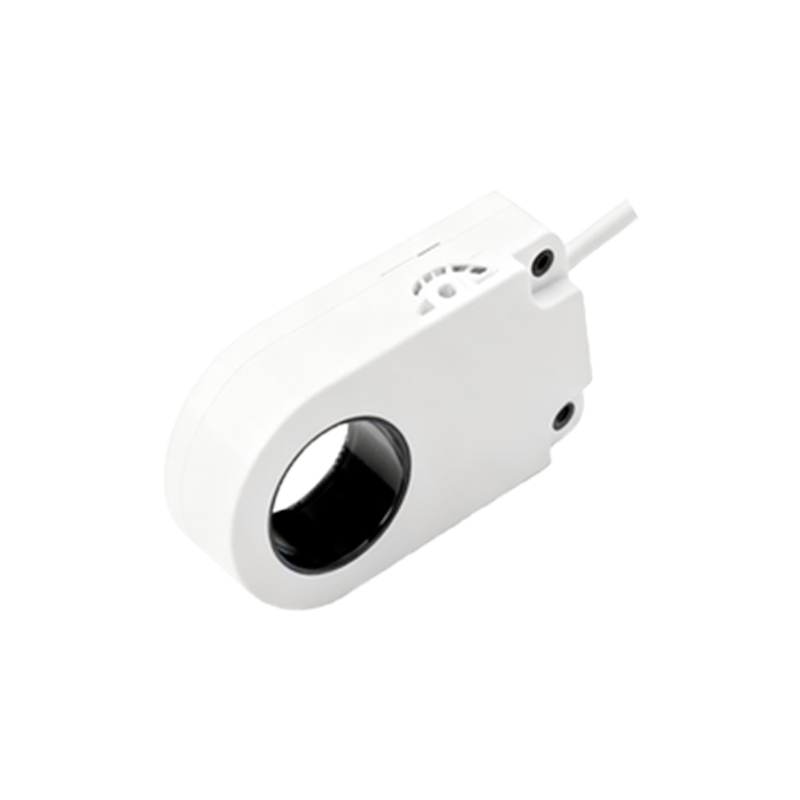
The conversion concept hinges on this reflective principle. A basic light sensor is passive; it only receives light. To make it sense proximity, we need to add an active light source, typically an Infrared (IR) LED, and configure the sensor to primarily detect the reflected light from this source, rather than ambient light. The key is to position the IR LED and the light sensor (now acting as an IR receiver) close together and facing the same direction. When an object comes near, the IR light from the LED reflects off the object and strikes the sensor, causing a measurable change in its output signal.
For this project, an IR-sensitive phototransistor is the ideal choice for the light sensor due to its fast response and sensitivity to the IR spectrum, which is invisible to the human eye. A standard photoresistor can be used but may be slower and more susceptible to ambient light interference. You will need an IR LED, a phototransistor, appropriate current-limiting resistors, and possibly an operational amplifier (op-amp) for signal conditioning.
The basic circuit involves two parts. First, the IR LED is connected in series with a current-limiting resistor (e.g., 100Ω) to a power source, ensuring it emits light consistently. Second, the phototransistor is connected. One common configuration is to connect the collector of the phototransistor to the positive supply through a load resistor (e.g., 10kΩ) and the emitter to ground. The voltage at the collector node becomes your output signal. When no object is present, the phototransistor receives minimal reflected IR light, so it conducts little current, and the output voltage is relatively high. When an object is close, reflected IR light increases the phototransistor's conductivity, causing more current to flow and the output voltage at the collector to drop.
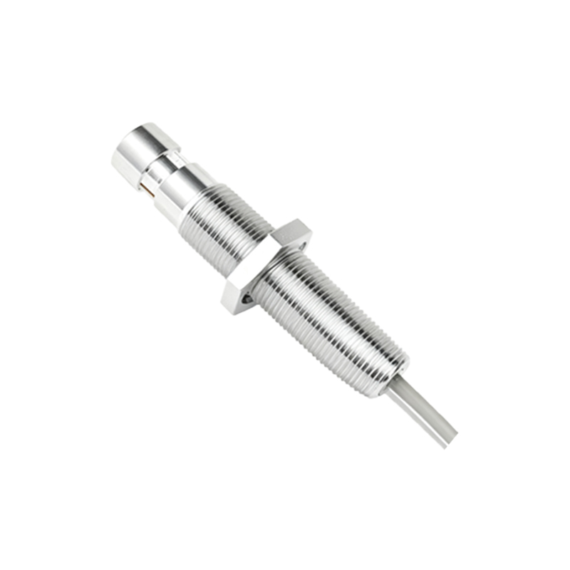
A major challenge is distinguishing the reflected IR signal from ambient light, which also contains IR components. Several strategies mitigate this. Using a modulated IR signal is the most effective professional technique. This involves pulsing the IR LED at a high frequency (e.g., 38kHz) and then tuning the receiving circuit to only amplify signals at that specific frequency. Ambient light, being generally constant or slowly changing, is filtered out. For simpler projects, physical shielding is crucial. Building a small tube or barrier between the IR LED and the phototransistor can minimize direct cross-talk and shield both from side ambient light. Focusing on the change in the sensor's output, rather than its absolute value, through comparator circuits, can also improve reliability.
To implement a basic version, follow these steps: 1) Solder the IR LED and phototransistor onto a small board, placing them 5-10mm apart. 2) Use black heat-shrink tubing or epoxy to create a short, separate barrel for each component to prevent direct light leakage. 3) Build the driver circuit for the IR LED and the biasing circuit for the phototransistor as described. 4) Connect the output voltage signal to the input of a comparator chip (like an LM393). Set the comparator's reference voltage with a potentiometer to a level corresponding to "no object present." 5) When an object approaches, the voltage drop will trigger the comparator's output to switch states, providing a clear digital signal indicating proximity.
Testing and calibration are essential. Power the circuit and use a voltmeter to monitor the phototransistor's output voltage. Observe the voltage as you move a non-shiny object (like white paper) towards and away from the sensor pair. Adjust the potentiometer controlling the comparator's reference voltage until the output reliably switches at your desired detection distance. Remember, the maximum range will be limited, typically a few centimeters, and is affected by object color, reflectivity, and ambient IR noise.
This conversion project demonstrates elegant engineering principles: repurposing components, understanding noise mitigation, and designing for a specific