In modern industrial automation, the integration of proximity sensors with Programmable Logic Controllers (PLCs) forms a critical link for reliable machine control and data acquisition. Proximity sensors, which detect the presence or absence of an object without physical contact, provide the essential input signals that a PLC uses to make logic-based decisions. The connection process, while systematic, requires careful attention to electrical compatibility, wiring standards, and configuration to ensure a robust and fail-safe operation.
The first step involves selecting the appropriate type of proximity sensor for the application. The two primary categories are based on their output signal: digital (discrete) and analog. Digital sensors, the most common type for basic detection tasks, provide a simple ON/OFF signal, typically indicating an object is within or outside the detection range. These are further classified by their output transistor type: NPN (sinking) or PNP (sourcing). Analog sensors output a continuous signal, such as 0-10V or 4-20mA, proportional to the distance of the target, used for precise positioning or measuring applications. The sensor choice directly dictates the wiring method and the type of PLC input module required.
A standard discrete DC sensor connection to a PLC input module involves three key wires: the power supply positive (brown), the power supply negative/ground (blue), and the output signal wire (black). For a PNP sensor (sourcing), the black wire outputs a positive voltage (e.g., +24V) when activated. This wire is connected directly to a specific PLC digital input point. The common terminal of that PLC input group is then connected to the power supply negative (0V). This completes the circuit: when the sensor detects an object, it sources current from its output, through the PLC input, and back to the negative supply, signaling a logic HIGH (1) to the PLC.
Conversely, an NPN sensor (sinking) operates differently. When activated, its black output wire connects internally to the negative supply (0V). This wire is connected to the PLC input point. The common terminal of the PLC input group must be connected to the positive supply (+24V). Thus, when the sensor detects an object, it sinks current from the PLC input (which is internally pulled high) down to 0V, signaling a logic LOW (0) to the PLC. It is absolutely crucial to match the sensor type (PNP/NPN) with the PLC input circuit configuration; a mismatch will prevent the system from functioning and could potentially cause damage.
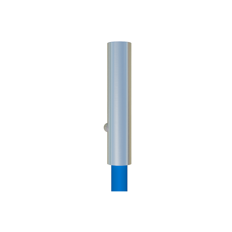
Wiring practices are paramount for noise immunity and safety. Always use shielded cables for sensor connections, especially in environments with motors or variable frequency drives. Connect the cable shield to a proper functional earth ground at the PLC cabinet, but only at one end to avoid ground loops. Maintain separation between power cables and sensor signal cables. Fuses or circuit breakers should be installed on the power supply line to the sensor to protect against short circuits. Most sensors have an LED indicator that provides immediate visual confirmation of power and output status, which is invaluable for troubleshooting.
Once physically wired, the configuration continues within the PLC programming software. The engineer must define the specific input address (e.g., I0.0, X1) assigned to the sensor's physical connection point. In the ladder logic or function block diagram, this input address becomes a contact. The logic is then programmed: for example, a normally open contact from input I0.0 might be used to energize an output coil to start a conveyor motor when a part is detected. For analog sensors, the PLC program must include instructions to scale the raw analog input value (e.g., 0-27648 for a 4-20mA signal) into meaningful engineering units like millimeters.
Testing and commissioning form the final, critical phase. After ensuring all power is off, double-check all wiring connections against the electrical diagram. Apply power and observe the sensor's LED. Test the sensor's function by introducing a target object into its sensing field. Monitor the PLC's input status LEDs or use the online monitoring feature of the programming software to verify that the correct input bit toggles. Finally, run the machine or process in a controlled manner to validate that the entire system reacts as programmed based on the sensor's signal. Proper documentation of all connections and addresses is essential for future maintenance.

By meticulously following these steps—selecting compatible components, executing correct wiring, and implementing precise PLC logic—technicians and engineers can establish a reliable interface between proximity sensors and PLCs. This synergy is the foundation for automated systems that are efficient, accurate, and capable of sophisticated industrial control tasks, from simple packaging lines to complex robotic assembly cells.