Proximity switch sensors are indispensable components in modern industrial automation, providing non-contact detection of metallic and sometimes non-metallic objects. Their reliability and longevity hinge on correct installation and precise adjustment. A misadjusted sensor can lead to false triggers, missed detections, and costly production downtime. This guide outlines the fundamental steps and considerations for properly adjusting these critical devices to ensure they operate at peak efficiency.
The initial step is always to consult the manufacturer's datasheet. This document contains vital specifications such as the sensor's nominal sensing distance (Sn), the assured operating distance (Sa), and any hysteresis values. The nominal sensing distance is a theoretical value under ideal conditions, while the assured operating distance accounts for variables like supply voltage fluctuations and temperature changes, typically being 70-80% of Sn. Never assume a sensor can reliably detect at its full nominal range in a real-world application.
Mounting is the first physical adjustment. Ensure the sensor is securely fixed in its bracket. For inductive sensors (detecting metals), pay close attention to the mounting geometry. Flush-mountable sensors can be embedded in metal without issue, whereas non-flush sensors require a clear zone around their sensing face—ignoring this can drastically reduce the effective sensing range. For capacitive sensors (detecting various materials), be mindful of the surrounding environment, as nearby objects or moisture can affect sensitivity.
Powering the sensor correctly is non-negotiable. Connect it to the specified DC or AC voltage. An unstable power supply is a common source of erratic behavior. Once powered, the primary adjustment is setting the sensitivity or detection threshold. Many modern sensors feature a potentiometer or a teach-in function for this purpose.
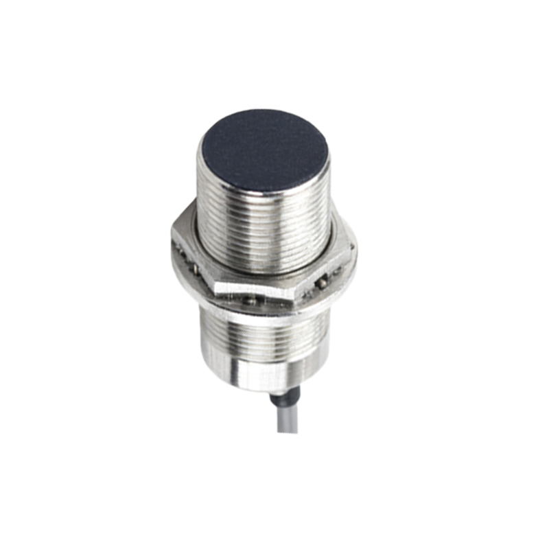
To adjust using a potentiometer, follow this procedure: First, position the target object (the standard object specified in the datasheet, often a square of mild steel for inductive types) at the desired detection point. Slowly rotate the adjustment screw counter-clockwise until the sensor's output indicator (usually an LED) turns off. Then, rotate the screw clockwise very slowly. The exact moment the indicator lights up steadily marks the detection threshold. For added reliability, continue rotating clockwise slightly further (increasing sensitivity) and then back off by about 10-15%. This provides a safety margin against minor variations in target position, material, or environmental conditions.
For sensors with a teach-in button, the process is more straightforward. Place the target in the desired "detect" position and press the button. Then, move the target to the desired "non-detect" position (or remove it entirely) and press the button again. The sensor's internal logic will calculate and set the optimal threshold between these two states.
After setting sensitivity, you must verify the adjustment under real operating conditions. Cycle the target object through its normal path multiple times. Check for consistent activation at the required point. It is crucial to test with all potential target variations that may appear in the process. For instance, if the line handles different metal alloys, test each type as their electrical properties can influence the sensing distance of an inductive sensor.
Environmental factors are persistent challenges. Temperature swings, accumulation of dust, oil, or metal shavings on the sensor face, and strong electromagnetic interference from nearby motors or welders can all degrade performance. Regular maintenance checks are essential. Periodically clean the sensing face with a soft cloth. Re-verify the sensing distance and sensitivity during seasonal temperature changes or after any significant changes to the machinery layout.
Finally, integrate the sensor's output with the control system (PLC, relay, etc.) and observe its behavior over an extended period. Monitor for any chattering (rapid on/off switching) or failure to trigger. Logging these events can help diagnose subtle adjustment issues.
Proper adjustment is not a one-time event but an integral part of preventive maintenance. By methodically following these steps—understanding specifications, correct mounting, careful sensitivity setting, thorough testing, and environmental compensation—you can maximize the service life of your proximity sensors and maintain the high reliability demanded in automated systems. A well-adjusted sensor is a silent guardian of productivity, ensuring seamless operation and protecting valuable machinery from collisions or process errors.