Inductive proximity sensors are fundamental components in modern industrial automation, offering non-contact detection of metallic objects. Their reliability, durability, and speed make them indispensable in manufacturing, packaging, and material handling. Understanding the various models available is crucial for optimal system performance. This guide delves into the key specifications, types, and selection criteria for inductive proximity sensor models.
The core principle of an inductive sensor involves an oscillator circuit generating a high-frequency electromagnetic field from its sensing face. When a metallic target enters this field, eddy currents are induced within the target, causing a load on the oscillator. This change is detected by the sensor's circuitry, which then switches its output state. This physical principle remains constant, but the implementation varies significantly across models.
Key Specifications Defining Models
Models are primarily differentiated by their technical specifications. The sensing distance, or nominal range, is a primary differentiator. Standard models offer ranges from 1mm to 60mm, with specialized versions for longer ranges. It is critical to note that the sensing distance is rated for a standard mild steel target. Factors like target material, size, and shape can affect the actual range; for instance, stainless steel may reduce it by 10-30%, while copper or aluminum can reduce it by up to 50%.
Output configuration is another major factor. Models come with digital outputs, typically NPN (sinking) or PNP (sourcing) transistor outputs. Some advanced models provide analog outputs (4-20 mA or 0-10 V) proportional to the distance to the target, useful for positioning applications. The housing material, usually nickel-plated brass, stainless steel, or PBT plastic, defines the model's suitability for harsh environments involving coolants, oils, or washdowns.
Common Model Form Factors
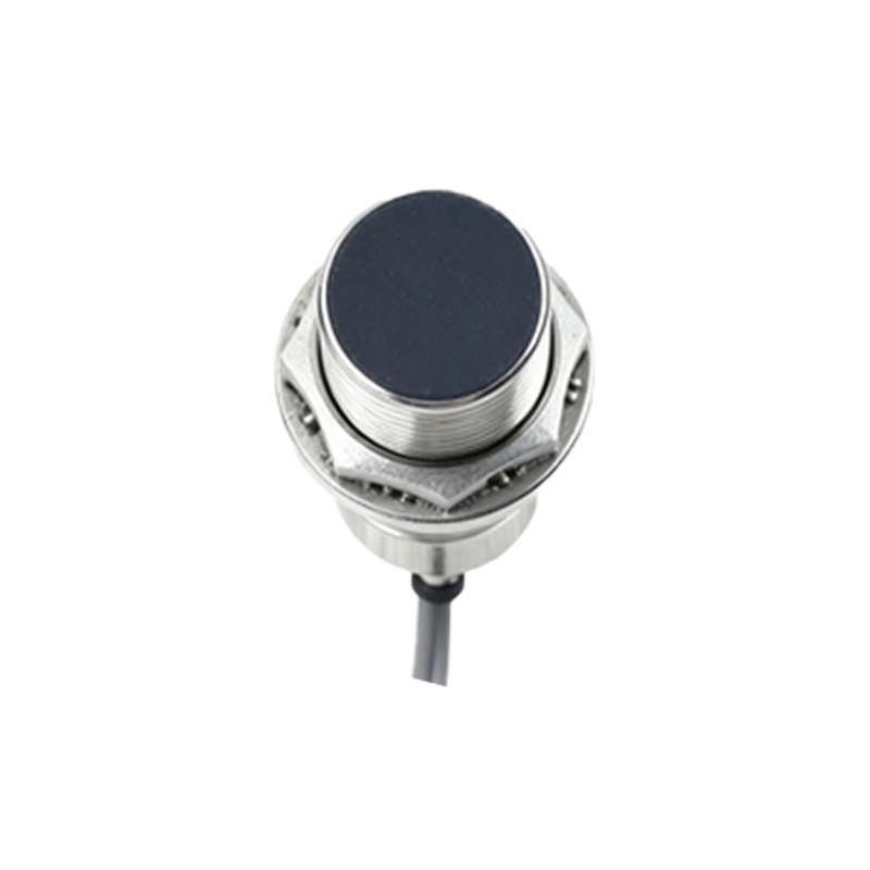
1. Cylindrical (Barrel) Sensors: The most ubiquitous form factor. Models are defined by their thread size (e.g., M8, M12, M18, M30) and length. They are easy to install and are used for general-purpose detection.
2. Rectangular (Block) Sensors: These models offer a more compact design in one dimension and often provide longer sensing ranges from the narrow face. They are ideal for space-constrained applications.
3. Slot Sensors (Fork Sensors): These models have a C-shaped or forked design where the target passes through the slot. They are excellent for detecting small parts, tabs, or teeth on gears.
4. Ring and Frame Sensors: Designed for detection of objects passing through their center aperture, these models are used for wire break detection, part counting on conveyors, or verifying the presence of components.
Specialized Model Variants
Beyond standard detection, specialized models address unique challenges:
Factor 1 Models: These sensors have a constant sensing distance regardless of the target material (ferrous or non-ferrous). They simplify installation and are used when target material may vary.
Weld-Field Immune Models: Specifically designed for robotic welding environments, these models are shielded against the strong magnetic fields generated by welding equipment, preventing false triggering.
High-Temperature Models: Built with specialized components and housing to withstand ambient temperatures exceeding 100°C, often found in foundries or near heat treatment processes.
Cylindrical Sensors with Extended Sensing Ranges: Some cylindrical models are engineered to offer 2-3 times the standard range of their form factor, providing flexibility in mounting.
Selection Criteria for the Right Model
Choosing the correct model requires a systematic assessment of the application:
1. Target Material: Determine if the target is mild steel, stainless steel, aluminum, copper, or brass. This directly impacts the effective sensing range.
2. Required Sensing Distance: Choose a model with a nominal range 10-20% greater than the maximum required installation gap to account for system tolerances and wear.
3. Installation Space and Environment: Consider the available physical space for mounting (dictating cylindrical or rectangular form) and the environmental conditions (requiring specific IP ratings, housing materials, or weld-field immunity).
4. Electrical Requirements: Match the sensor's operating voltage (commonly 10-30V DC) and output type (NPN/PNP) to the control system's input card specifications. Ensure the load current does not exceed the sensor's rating.
5. Response Frequency: For high-speed applications like counting small parts on a fast conveyor, select a model with a high switching frequency (often up to 5 kHz).
Proper installation is the final step to ensuring model performance. Always maintain a clearance between the sensor face and the metal mounting bracket, as specified in the datasheet, to prevent side-interference. Ensure the target approaches