Wiring proximity sensors in series is a common practice in industrial automation to monitor multiple points with a single input on a PLC or controller. This method can simplify wiring, reduce hardware costs, and streamline system design. However, it requires careful planning to ensure reliable operation. Here’s a step-by-step guide on how to properly connect proximity sensors in series.
First, understand the basic principle. When sensors are wired in series, their output signals are connected in a chain, so the circuit is only complete when all sensors are activated. If any sensor in the series fails or does not detect a target, the entire circuit opens, and no signal is sent. This is useful for applications where all sensors must agree on a condition, such as safety interlocks or multi-point verification systems.
Before starting, gather the necessary components: proximity sensors (ensure they are of the same type and voltage rating, typically DC sensors like NPN or PNP), a power supply matching the sensor specifications, cables, connectors, and a multimeter for testing. Always refer to the manufacturer’s datasheets for specific wiring details, as configurations may vary.
For DC sensors, the wiring process differs between NPN (sinking) and PNP (sourcing) types. In an NPN sensor series connection, connect the positive wire from the power supply to the positive terminal of the first sensor. Then, link the output terminal of the first sensor to the positive terminal of the next sensor, continuing this pattern for all sensors. Finally, connect the output of the last sensor to the PLC input, and link all negative terminals together to the power supply’s negative line. This creates a chain where current flows only when all sensors are on.
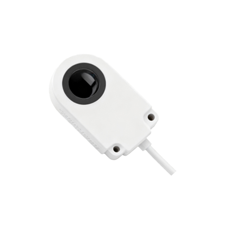
For PNP sensors, the approach is similar but reversed. Connect the negative wire from the power supply to the negative terminal of the first sensor. Link the output of the first sensor to the negative terminal of the next, and so on. The output of the last sensor goes to the PLC input, with all positive terminals tied to the power supply’s positive line.
Key considerations include voltage drop. Each sensor in series adds resistance, which can lower the voltage reaching the PLC. To avoid issues, calculate the total voltage drop based on sensor specifications and ensure it stays within the PLC’s input range. Using a higher voltage power supply might be necessary, but never exceed the sensors’ rated limits. Also, check the current rating to prevent overload.
Reliability is crucial. Series wiring means a single faulty sensor can disable the entire circuit. Implement regular maintenance and testing to identify problems early. For critical applications, consider adding diagnostic indicators or using parallel wiring for redundancy instead.
In summary, wiring proximity sensors in series is effective for coordinated control but demands attention to detail. Always test the circuit with a multimeter before full deployment, verifying that each sensor triggers correctly and the signal reaches the PLC as expected. By following these guidelines, you can achieve a robust and efficient automation setup.