In the world of industrial automation and machine control, proximity sensors are indispensable components. Among the various types, PNP proximity switch sensors hold a significant place due to their specific operating logic and wiring configuration. This guide delves into the fundamentals, working principles, applications, and key considerations for PNP proximity sensors, providing a clear understanding for engineers, technicians, and enthusiasts.
At its core, a proximity sensor is a non-contact device that detects the presence or absence of an object within its sensing range. Unlike mechanical limit switches, they operate without physical contact, leading to higher reliability and longer service life. Proximity sensors are commonly categorized by their sensing technology, such as inductive, capacitive, or photoelectric. The PNP designation, however, refers specifically to the type of transistor output and the associated wiring scheme.
PNP stands for "Positive-Negative-Positive." In a PNP sensor, the output transistor is configured to switch the positive voltage supply line. When the sensor is in its normal state (no target detected), the output signal line is effectively disconnected from the positive supply. Upon detecting a target object within its sensing field, the internal transistor switches on, connecting the output signal line to the positive supply voltage (e.g., +24V DC). This means the sensor "sources" current to the load. The load (such as a PLC input, relay, or indicator light) is connected between the sensor's output wire and the common negative (0V) line. Consequently, when activated, the output wire becomes "high" or "positive."
This is often contrasted with NPN (Negative-Positive-Negative) sensors, which switch the negative or ground line. A simple way to remember is: PNP sensors provide a Positive signal when activated. This sourcing characteristic makes PNP sensors the standard and often preferred choice in many European and Asian regions, particularly in PLC systems where inputs are commonly configured to receive a sourcing (PNP) signal.
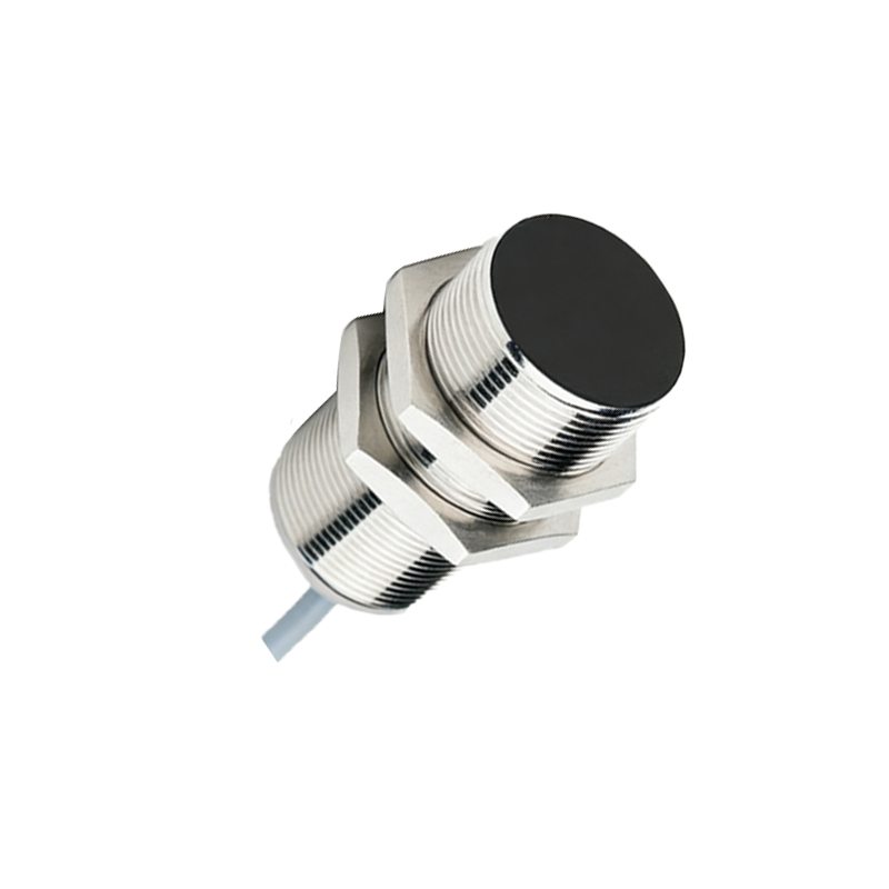
The operation of an inductive PNP proximity sensor, one of the most common types, is based on electromagnetic induction. The sensor's face contains an oscillator circuit that generates a high-frequency electromagnetic field. When a metallic target enters this field, eddy currents are induced in the target, causing a change in the oscillation amplitude. This change is detected by the sensor's circuitry, which then triggers the switching of the PNP output transistor. The sensor reliably detects ferrous and non-ferrous metals, though sensing distances may vary with material type.
Key specifications for selecting a PNP proximity sensor include sensing distance, supply voltage range, output current capacity, switching frequency, housing material (often nickel-plated brass or stainless steel for durability), and environmental protection ratings like IP67 for resistance to dust and water immersion. The "normally open" (NO) or "normally closed" (NC) configuration defines the output state in the absence of a target. A PNP-NO sensor has no output (0V) when idle and provides +V when a target is detected.
Applications for PNP proximity switches are vast across manufacturing and processing industries. They are used for object detection on conveyor belts, counting products, monitoring the position of machine parts (like cylinder rods), ensuring safety in automated systems, and verifying the presence of tools in CNC machines. Their robust, non-contact nature makes them ideal for harsh environments with vibration, moisture, or airborne contaminants.
When integrating a PNP sensor into a control system, correct wiring is paramount. The typical three-wire DC sensor has brown (positive supply +V), blue (common negative 0V), and black (output signal) wires. The brown wire connects to the positive DC supply, the blue wire to the negative, and the black output wire connects to the load. The other side of the load is then connected back to the negative supply. It is crucial to ensure the power supply voltage matches the sensor's rating and that the load current does not exceed the sensor's maximum switching capacity. A protective fuse or circuit breaker is recommended in the supply line.
Troubleshooting often involves checking for power at the sensor, verifying the target is within the rated sensing distance and is of an appropriate material, and inspecting the output with a multimeter or indicator. A common mistake is mixing PNP and NPN sensors with incompatible PLC input modules, leading to non-operation.
In summary, PNP proximity switch sensors are vital sourcing-type devices that provide a positive voltage signal upon detection. Their design offers reliable, wear-free operation for countless position sensing and object detection tasks. Understanding their "sourcing" output logic, alongside factors like sensing technology, environmental ratings, and correct wiring practices, is essential for their successful implementation in modern automated systems, ensuring efficiency, safety, and reliability on the factory floor.