Proximity sensors are widely used in industrial automation, robotics, and safety systems to detect the presence or absence of objects without physical contact. Proper wiring is crucial for ensuring reliable operation and preventing damage to the sensor or connected equipment. This guide covers common wiring methods for different types of proximity sensors, including inductive, capacitive, and photoelectric variants.
Most proximity sensors operate on DC or AC power supplies, typically ranging from 10-30V DC or 90-250V AC. The wiring configuration depends on the sensor's output type: NPN (sinking) or PNP (sourcing). In NPN configurations, the load is connected between the positive supply and the sensor output, while the sensor acts as a switch to ground. This setup is common in Asian and European markets. For PNP configurations, the load connects between the sensor output and ground, with the sensor switching the positive supply. PNP wiring is often preferred in North America.
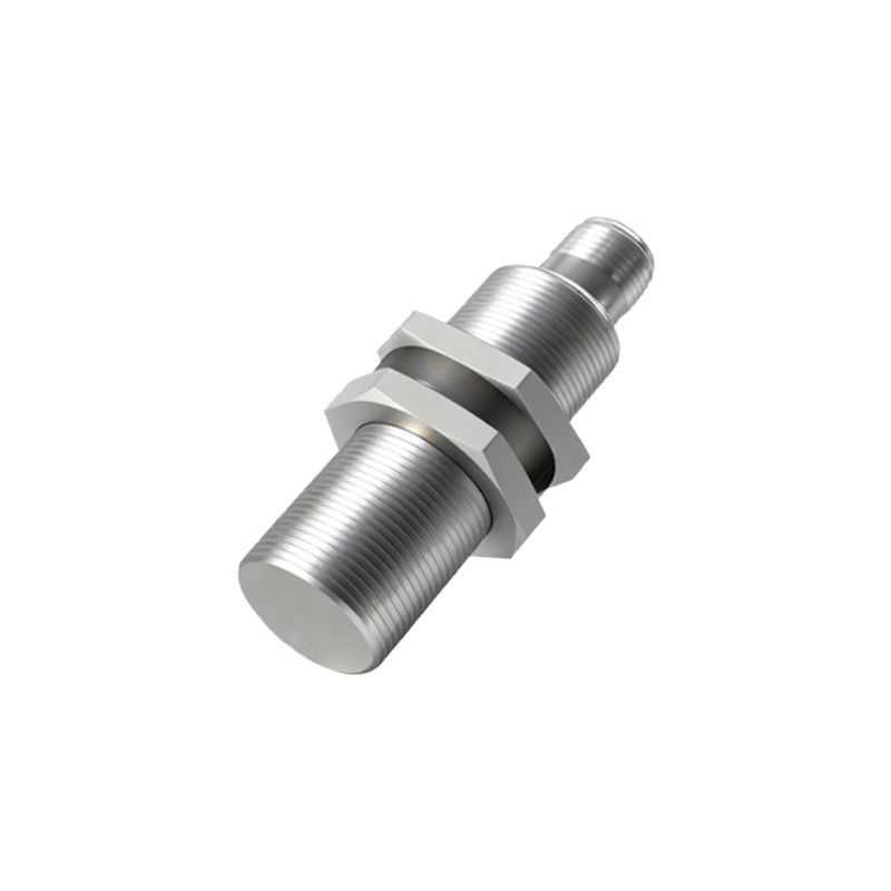
Three-wire proximity sensors include power (brown wire), ground (blue wire), and output (black wire) connections. The brown wire connects to the positive terminal for DC sensors or the live terminal for AC sensors. The blue wire links to the negative or neutral terminal, while the black wire delivers the switched output to the load, such as a PLC input or relay. For two-wire sensors, wiring is simpler: one wire connects to power, and the other serves as both output and return path. However, two-wire sensors may have higher voltage drops and leakage currents, which can affect performance with sensitive loads.
Shielded cables are recommended for long cable runs or electrically noisy environments to prevent interference. The cable shield should be grounded at one end only, typically at the control panel. Additionally, ensure proper separation from high-voltage cables—maintain at least 30 cm of distance to avoid inductive coupling. For AC-powered sensors, incorporate fuses or circuit breakers rated slightly above the sensor's current consumption to protect against short circuits.
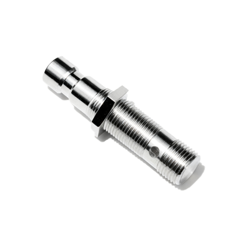
When connecting multiple sensors, avoid daisy-chaining power wires directly from one sensor to another. Instead, use a dedicated power distribution block to ensure stable voltage supply. For output connections, verify the load compatibility with the sensor's output current and voltage ratings. Overloading can cause premature failure or erratic behavior. Some sensors feature diagnostic LEDs that indicate power status and output activation, aiding in troubleshooting.
Environmental factors also influence wiring choices. In humid or corrosive settings, use sensors with IP67 or higher ingress protection ratings and seal cable entries with gland fittings. For high-temperature applications, select heat-resistant cables and avoid routing wires near hot surfaces. Always refer to the manufacturer's datasheet for specific wiring diagrams and specifications, as pin assignments or color codes may vary by brand.
Testing the installation with a multimeter or oscilloscope can confirm proper voltage levels and signal integrity. Check for voltage drops under load and ensure the output switches cleanly without oscillation. Regular maintenance, including inspecting connections for corrosion or looseness, extends sensor lifespan and prevents downtime. By following these wiring practices, users can optimize sensor performance and enhance system reliability in diverse operational conditions.