Proximity sensors are critical components in modern industrial automation, consumer electronics, and automotive systems. These non-contact devices detect the presence or absence of objects within a defined range, triggering subsequent actions in a machine or system. A malfunctioning proximity sensor can lead to production line stoppages, safety hazards, or device failures. Understanding how to diagnose and repair common proximity sensor anomalies is essential for maintenance technicians and engineers.
The initial step in addressing a suspected proximity sensor issue is accurate diagnosis. Symptoms of failure are varied. The most common is a complete lack of response—the sensor fails to detect a target within its specified sensing range. Conversely, a sensor might trigger erratically, activating without a target present (false positive) or failing to activate with a valid target (false negative). Intermittent operation, where the sensor works sporadically, is another frequent complaint. Before concluding the sensor itself is faulty, a systematic troubleshooting approach is required.
First, verify the basics. Ensure the sensor has correct and stable power supply voltage as per its datasheet specifications. Use a multimeter to check voltage at the sensor's terminals under load. Voltage drops or electrical noise on the supply line are common culprits. Next, inspect the physical installation. Misalignment between the sensor and its target can cause failures. Check for proper mounting, ensuring the sensing face is correctly oriented and free from obstructions like dirt, metal shavings, or thick paint. The sensing distance can degrade if the target object is smaller, or made of a different material, than the sensor was calibrated for. For inductive sensors, only metallic targets are detected; for capacitive sensors, the target material matters less but environmental factors matter more.
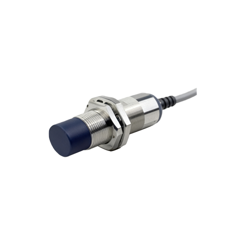
Environmental factors are a major source of "abnormal" behavior. Strong electromagnetic interference (EMI) from nearby motors, welders, or power lines can disrupt sensor operation. Excessive ambient temperature, beyond the sensor's rated operating range, can cause drift or failure. For optical proximity sensors, contamination like dust, oil, or fog on the lens will impair function. Similarly, ultrasonic sensors can be affected by air turbulence or high noise levels in the same frequency range.
Wiring and connections demand careful scrutiny. Loose terminals, corroded contacts, or damaged cables can create intermittent faults. Check for short circuits, open circuits, or ground faults. Examine the cable for pinch points or wear, especially in applications with continuous movement. The load connected to the sensor's output (e.g., a PLC input, relay, or solenoid) must be within its current and voltage ratings. An overloaded output can damage the sensor's internal switching circuit.
If basic checks yield no results, consult the sensor's indicator LED (if equipped). Most sensors have a power LED and a switching-state LED. Their behavior—solid, blinking, or off—can provide diagnostic clues as outlined in the manufacturer's manual. For a more advanced check, use an oscilloscope to examine the output signal's waveform for noise or irregularities.
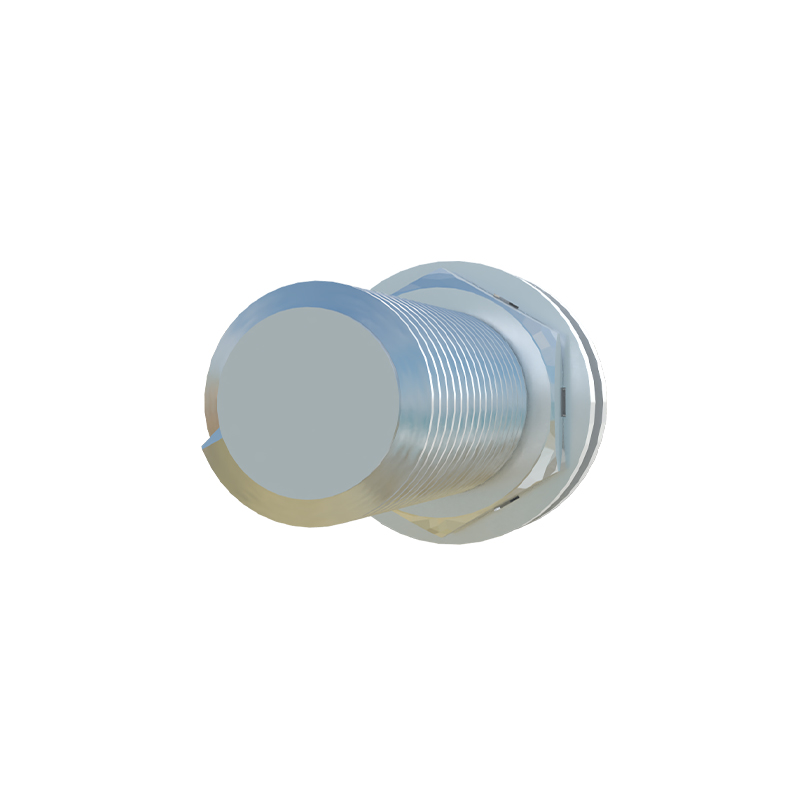
When repair is necessary, often the only option for sealed, solid-state sensors is complete replacement. However, for some units, specific actions are possible. Cleaning is the most straightforward repair. Gently clean the sensing face with a soft, lint-free cloth and appropriate cleaner (isopropyl alcohol for optics, degreaser for inductives). Never use abrasive materials. For sensors with adjustable sensing ranges or sensitivity pots, a recalibration might restore function. Using the manufacturer's procedure, adjust the potentiometer while testing with a standard target at the required distance.
In cases of damaged wiring, the cable or connector can sometimes be replaced if the sensor housing allows it. Ensure the replacement cable has the same specifications and shielding. For sensors integrated into complex assemblies, board-level repair might be attempted by skilled technicians, focusing on the output transistor or voltage regulator, which are common failure points. However, the cost and time of such repairs often outweigh replacement.
Preventive maintenance is key to avoiding unexpected failures. Establish a regular schedule to clean sensors, check mounting integrity, and verify electrical connections. Monitor environmental conditions and consider installing protective shields or barriers where contamination or physical damage is likely. Keep a stock of critical spares to minimize downtime.
Ultimately, successful repair hinges on a logical process: observe the symptom, check power and environment, inspect physical and electrical connections, interpret diagnostic aids, and perform targeted corrective actions. When a sensor is repeatedly failing, consider whether it is the correct type for the application and whether a more robust model with a higher IP rating, wider temperature tolerance, or immunity to specific interferences is required. Documenting failures and solutions builds a valuable knowledge base for future troubleshooting, ensuring smoother operations and reduced costly downtime across all systems reliant on these vital electronic sentinels.
SEO描述