In the world of industrial machinery monitoring and predictive maintenance, proximity probes stand as critical sentinels. These sophisticated sensors provide a non-contact method for measuring vibration and displacement in rotating equipment, offering unparalleled insights into machine health. But how exactly does a proximity probe work? This guide delves into the operational principles, components, and applications of this essential technology.
At its core, a proximity probe system is designed to measure the distance between the probe tip and a conductive target, typically a shaft or gear. It operates on the principle of eddy current induction. The system comprises three main components: the probe itself (the sensor), an extension cable, and a proximitor (the oscillator-demodulator or signal conditioner).
The magic begins within the proximitor. This electronic unit generates a high-frequency radio frequency (RF) signal, typically ranging from 500 kHz to 2 MHz. This signal is sent down the coaxial extension cable to the coil housed in the probe tip. When this energized coil is brought near a conductive material—the machine's shaft—it generates a magnetic field. This alternating magnetic field induces circular electrical currents, known as eddy currents, on the surface of the conductive target.
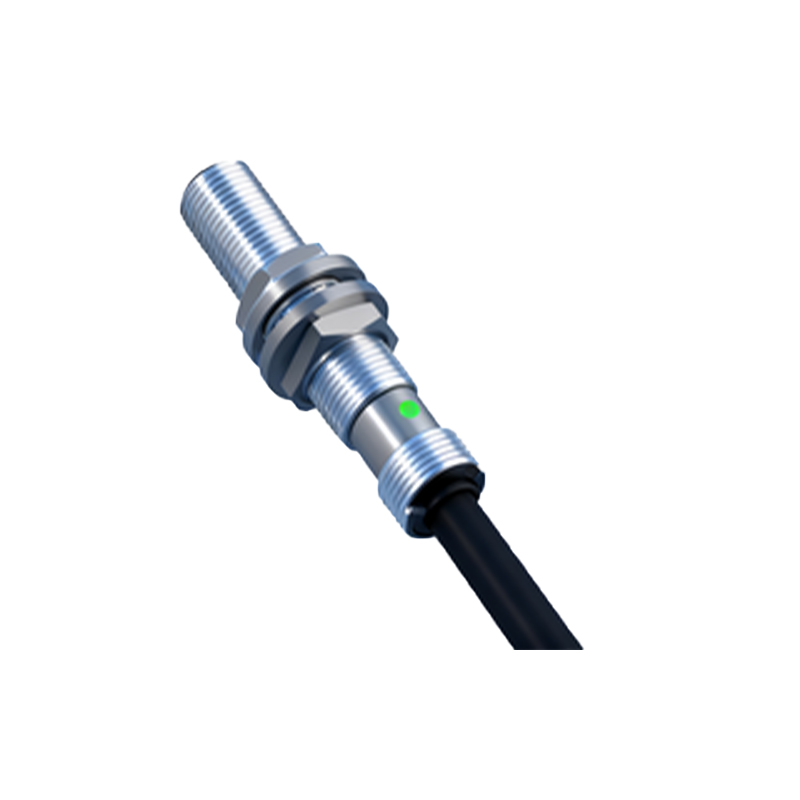
The interaction between the probe's magnetic field and the induced eddy currents is key. The eddy currents generate their own opposing magnetic field. The strength of this opposing field depends on the distance between the probe tip and the target. As the gap decreases, more eddy currents are induced, creating a stronger opposing magnetic field. As the gap increases, the effect weakens.
This change in the magnetic interaction directly affects the impedance (a combination of resistance and inductance) of the coil in the probe. The proximitor continuously monitors this impedance. It effectively demodulates the high-frequency signal, stripping away the carrier frequency to extract the meaningful data: the change in the gap distance. This raw signal is then converted into a precise, proportional DC voltage output. A common scaling is 200 millivolts per mil (0.001 inch) or 8 millivolts per micron. This voltage signal is what is sent to monitoring systems, data collectors, or control units.
The output provides two primary types of information. First, the DC or average voltage component represents the average gap or static position of the shaft within its bearing (e.g., for checking bearing clearance). Second, the AC voltage component represents the dynamic motion—the vibration—of the shaft as it rotates and moves within the gap. This allows technicians to see both slow-roll runout and dynamic vibration frequencies.
The choice of target material is crucial for optimal operation. Ferrous materials like steel provide a strong signal. Non-ferrous conductive materials like aluminum or copper also work well, though they may require system calibration adjustments as eddy currents penetrate deeper into these materials. The target must be large enough to cover the probe's sensing area and must be electrically conductive; non-conductive materials cannot be measured with standard eddy current probes.
Installation and setup are critical for accuracy. The probe must be mounted securely and precisely, often with a mounting bracket, to prevent its own vibration from affecting readings. The initial gap must be set correctly, typically within the probe's linear range, to ensure the voltage output is directly proportional to distance change. Proper grounding and shielding of the entire system are essential to prevent electrical noise from corrupting the sensitive measurement signal.
The applications for proximity probes are vast and vital. They are the primary sensors for measuring radial vibration in turbomachinery such as turbines, compressors, and large pumps in industries like power generation, oil and gas, and aviation. They are used to measure axial thrust position to prevent catastrophic damage from rotor float. Furthermore, they serve in speed measurement by observing key phasor marks on a shaft, providing a once-per-revolution timing pulse essential for vibration phase analysis.
Compared to contact sensors like velocity transducers or accelerometers, proximity probes offer distinct advantages. They measure the shaft's motion directly, not the casing's, providing a more accurate picture of the rotor dynamics. They require no physical contact, eliminating wear and allowing measurement on very high-speed machinery. They can measure both dynamic vibration and static position simultaneously.
Understanding how a proximity probe works empowers maintenance and reliability engineers to specify, install, and interpret data from these systems correctly. By converting minute changes in a magnetic field into precise electrical signals, these probes form the frontline defense in machinery health monitoring, enabling the shift from reactive breakdown maintenance to proactive, condition-based strategies that ensure safety, efficiency, and operational continuity.