Inductive proximity sensors are fundamental components in industrial automation, offering non-contact detection of metallic objects. Their operation hinges on electromagnetic induction, generating an oscillating electromagnetic field from a coil within the sensor's face. When a metallic target enters this field, eddy currents are induced on the target's surface. This causes a measurable change in the sensor's internal oscillation amplitude or frequency, triggering a switching output. The core performance specification is the rated sensing distance (Sn), defined under standardized conditions.
The rated sensing distance is not an absolute maximum. It is calibrated using a standard target—typically a square of mild steel (Fe360) with a thickness equal to the sensor's face diameter or 1mm, whichever is greater. The target must approach the sensor face perpendicularly. Under these ideal laboratory conditions, the sensor will reliably detect the target at the stated Sn value. Real-world application, however, introduces numerous factors that affect the actual usable sensing distance.
Several key factors influence performance. First is the target material. Different metals have different electrical conductivities and magnetic permeabilities. For a standard steel target, the factor is 1.0. For stainless steel (non-ferromagnetic), the effective sensing distance reduces to approximately 0.7 to 0.9 times Sn. For brass or aluminum, it drops further to about 0.4 to 0.5 times Sn. Copper sensing distance is even less. Ferrous materials (like standard iron and steel) are detected at the full rated distance or sometimes slightly more due to their high permeability.
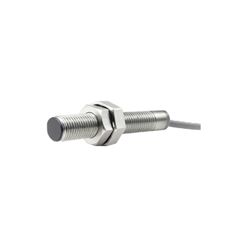
Target size and shape are equally critical. The standard target size is designed to fully interact with the sensor's electromagnetic field. If the target is smaller than the sensor's active face area, the sensing distance decreases proportionally. For instance, a target with half the required surface area may only achieve 60-70% of Sn. The shape also matters; rounded or irregular edges can slightly reduce the effective distance compared to a flat, square face.
Installation conditions significantly alter the sensing field. Inductive sensors are susceptible to metal in their immediate surroundings. When flush-mounted in a metal bracket (as designed), the lateral electromagnetic field is shielded, creating a focused forward detection zone. However, if non-flush mounted (with the sensor barrel exposed), surrounding metal can dampen the field, reducing the effective range. Manufacturers specify correction factors for non-flush mounting, often reducing usable distance to 50-80% of Sn. The presence of adjacent sensors or large metal structures can also cause mutual interference, necessitating adequate spacing.
Temperature fluctuations impact the electrical properties of the sensor's coil and oscillator circuit. Most industrial sensors are rated for operation from -25°C to +70°C. Within this range, a temperature drift specification, often ±10% of Sn, accounts for variations. Extreme temperatures outside the rated range can cause failure or significant inaccuracy. Voltage supply variations within the sensor's specified range typically have a minimal effect on sensing distance.
For optimal system design, engineers must apply derating factors. The effective operating distance (Sa) is calculated as: Sa = Sn x (Material Factor) x (Size Factor) x (Installation Factor). A safety margin, often 10-20%, is then applied to Sa to establish the practical installation distance, ensuring reliable operation despite minor misalignment, wear, or environmental changes. This prevents false triggers and system downtime.
Regular maintenance and calibration checks are advised, especially in harsh environments where buildup of metallic dust or chips on the sensor face can attenuate the sensing field, effectively reducing the range. Cleaning the sensor face with a non-abrasive cloth is a simple but crucial preventative measure. Understanding these principles allows for correct sensor selection, robust machine design, and maximized reliability in automated systems handling metal parts, from conveyor lines to robotic cells.