Proximity sensors are essential components in modern automation, enabling equipment to detect the presence or absence of objects without physical contact. Proper wiring is crucial for their reliable operation. This guide provides a clear, step-by-step approach to wiring common types of proximity sensors, focusing on practical application and safety.
Before starting any wiring work, always disconnect power to the circuit. Verify the voltage is off using a multimeter. Gather necessary tools: wire strippers, screwdrivers, and the sensor's datasheet. The datasheet is your most important reference—it specifies the sensor's type, voltage range, current rating, output configuration, and pinout.
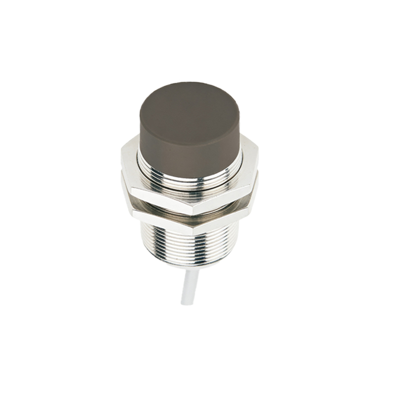
Most industrial proximity sensors fall into two main categories based on their output circuitry: 2-wire and 3-wire sensors. 4-wire sensors also exist, often combining different output types.
1. Wiring a 2-Wire Proximity Sensor
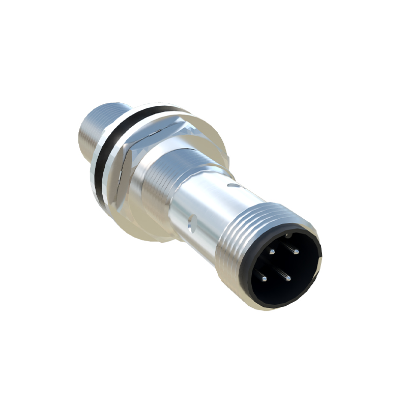
The 2-wire sensor is the simplest to connect. It acts like a switch in series with the power supply and the load (e.g., a PLC input, relay coil, or indicator lamp). The two wires are typically brown and blue.
Step 1: Identify the wires. According to international standards (IEC), the brown wire is for positive DC or Line for AC. The blue wire is for negative DC or Neutral for AC.
Step 2: Connect the brown wire to the positive terminal of your DC power supply or the Line (L) terminal for AC.
Step 3: Connect the blue wire to one terminal of your load (the device you want to control).
Step 4: Connect the other terminal of your load back to the negative side of the DC supply or the Neutral (N) for AC, completing the circuit.
Important: 2-wire sensors have a small leakage current even when "off." Ensure your load's impedance is low enough to prevent false triggering.
2. Wiring a 3-Wire Proximity Sensor
This is the most common type. It has three distinct wires: brown (power+), blue (power-), and a third wire (black, white, or gray) for the output signal.
Step 1: Connect the brown wire to the positive side of your DC power supply (typically +24V DC in industrial settings).
Step 2: Connect the blue wire to the negative side (0V or common) of the same power supply. This provides operating power to the sensor's internal electronics.
Step 3: The third wire is the output. You must know if it's a NPN or PNP type, as this determines the connection.
For a PNP Sensor (Sourcing): The black wire outputs positive voltage when activated. Connect it to your load (e.g., a PLC digital input). The other side of the load must then be connected to the power supply's negative (blue wire/0V).
For an NPN Sensor (Sinking): The black wire sinks current to negative when activated. Connect it to your load. The other side of the load must be connected to the power supply's positive (brown wire/+24V).
A simple mnemonic: "PNP, Positive Switched." The output provides the Positive signal.
3. Wiring a 4-Wire Proximity Sensor
A 4-wire sensor typically contains both a normally open (NO) and a normally closed (NC) output, or sometimes two independent outputs (e.g., one PNP and one NPN). The wiring follows the same logic as the 3-wire type.
Step 1 & 2: Connect the brown (+V) and blue (0V) power wires as described above.
Step 3: Identify the function of the remaining two wires (often black and white). The datasheet will label them as NO and NC. Connect them to your respective loads based on whether you need a circuit to close (NO) or open (NC) upon detection.
Critical Safety and Best Practices
Shielded Cable: In electrically noisy environments, use shielded cable. Connect the shield to ground at only one end (usually the control panel end) to prevent ground loops.
Fusing: Always protect the sensor circuit with a correctly rated fuse or circuit breaker.
Grounding: Ensure proper grounding of the metal housing of the sensor, especially for AC types or in high-noise areas.
Load Compatibility: Never exceed the sensor's maximum switching current. Check that the load's "on" current is above the sensor's minimum required load.
Polarity: