Laser sensors are critical components in modern automation, industrial control, and precision measurement systems. When a laser sensor malfunctions, it can disrupt entire production lines or data acquisition processes. Understanding how to diagnose and repair these devices is essential for technicians and engineers. This guide provides a systematic approach to laser sensor repair, focusing on practical steps and safety considerations.
The first step in any repair process is accurate diagnosis. Begin by verifying the symptoms. Common issues include no output signal, intermittent operation, inaccurate measurements, or a complete failure to power on. Before disassembling the sensor, perform basic external checks. Ensure the power supply voltage matches the sensor's specifications, typically ranging from 10-30V DC. Inspect the wiring and connectors for damage, corrosion, or loose connections. Cables are frequent points of failure, especially in environments with vibration or movement. Use a multimeter to check for proper voltage at the sensor's terminals and continuity in the cables.
Environmental factors often cause sensor problems. Accumulation of dust, dirt, or debris on the lens is a leading cause of performance degradation. Carefully clean the optical lens using a soft, lint-free cloth and an appropriate optical cleaner. Avoid abrasive materials or excessive pressure that could scratch the coating. Check for signs of moisture ingress or condensation inside the housing, which can severely damage internal electronics. If present, the sensor may require drying in a controlled environment and resealing.
If external checks don't resolve the issue, proceed to internal inspection after ensuring the device is disconnected from all power sources. Open the sensor housing carefully, noting the arrangement of components and cable routing. Visually inspect the internal printed circuit board (PCB) for obvious damage: burnt components, cracked solder joints, or corroded traces. Pay close attention to the laser diode module and the photodetector/receiver section. The laser diode is sensitive to electrostatic discharge (ESD); always use an anti-static wrist strap when handling it.
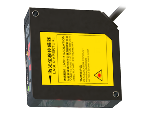
Testing the laser diode requires caution. Never look directly into the laser beam. Using a laser power meter is the safest method to check output. A significant drop in power output indicates a failing diode. Diode failure can be due to aging, current surges, or thermal stress. Replacing a laser diode is a delicate procedure. Note the diode's specifications (wavelength, power rating, package type) and desolder it carefully. When installing a new diode, ensure proper polarity and alignment. Thermal management is crucial; apply a thin layer of thermal compound and secure the diode to its heat sink properly.
The receiver circuit, which processes the reflected light, is another critical area. Test the photodetector (often a photodiode or phototransistor) by measuring its response to a light source. A weak or non-existent signal suggests a faulty detector. Signal conditioning components like amplifiers, filters, and comparators on the PCB should also be tested. Use an oscilloscope to trace the signal path from the detector to the output stage. Look for distorted or absent waveforms at each stage to isolate the faulty component.
Microcontrollers or dedicated ICs govern the sensor's logic and communication. Firmware corruption is rare but possible. If the sensor has a reprogrammable chip, check the manufacturer for firmware recovery procedures. More commonly, issues arise with supporting components: voltage regulators, capacitors, and oscillators. Swollen or leaking capacitors are a telltale sign of power supply problems. Replace them with identical specifications (capacitance, voltage rating, and type).
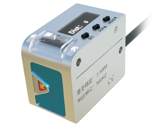
After replacing any components, perform a careful reassembly. Ensure all seals and gaskets are intact to maintain the sensor's ingress protection (IP) rating. Before reinstalling the sensor in its application, conduct a bench test. Power the sensor and verify its output using a known reference target at a set distance. Calibrate the sensor if necessary, following the manufacturer's instructions. This often involves adjusting potentiometers or using software tools to set thresholds and sensitivity.
Preventive maintenance can avoid many repairs. Establish a regular schedule for cleaning lenses and inspecting cables. Ensure the operating environment stays within the sensor's specified temperature, humidity, and vibration limits. Use protective housings or barriers in harsh conditions. Keep a log of sensor performance to identify gradual degradation.
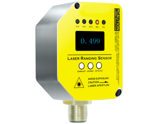
Not all repairs are economically viable. If the core optical module is damaged or the PCB is extensively corroded, replacement may be more cost-effective than repair. Always consult the sensor's technical manual and consider the cost of downtime versus the price of a new unit.
Mastering laser sensor repair requires a blend of electronic knowledge, optical understanding, and meticulous technique. By following a logical diagnostic sequence—from external checks to internal component analysis—technicians can restore functionality and extend the lifespan of these valuable instruments. Remember that safety, both personal and for the device, is paramount throughout the repair process.