Replacing a laser sensor, whether in an industrial automation setup, a consumer device like a laser printer, or a precision measurement tool, is a critical maintenance task. While the specific steps can vary greatly depending on the sensor model and its application, the general process follows a logical sequence of safety, removal, installation, and calibration. This guide, designed to accompany a detailed video tutorial, outlines the universal principles and precautions you should know before attempting a replacement.
The most important step always comes first: ensuring complete safety. Laser sensors, even low-power ones, can pose a risk to eyesight. Before any work begins, you must disconnect all power sources to the machine or system—this means locking out and tagging out electrical panels in industrial environments. Never assume a device is off; always verify with a multimeter. Allow any capacitors in the system to discharge fully. Put on appropriate personal protective equipment (PPE), such as safety glasses designed for the specific laser wavelength. Consult the sensor's datasheet and the machine's manual for any model-specific warnings.
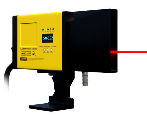
Once safety is secured, the diagnostic phase begins. Confirm that the sensor itself is the issue. Common symptoms of a failing laser sensor include inconsistent readings, a complete lack of output signal, physical damage to the lens or housing, or error codes on the controller. Use the manual to run basic diagnostics if possible. Check the wiring, connectors, and power supply, as these are often the root cause of perceived sensor failures. Document the existing setup thoroughly. Take clear, well-lit photographs or a video of the sensor's mounting, its orientation, and every wire connection. Label each cable with tape if they are not already identified. This visual record is invaluable during reinstallation.
The removal process requires patience and the right tools. Typically, you'll need a set of precision screwdrivers, hex keys, and possibly a small wrench. Gently disconnect the electrical cables. Note the connector type—some may have locking tabs that require careful pressing to release. Avoid pulling on the wires themselves. Next, loosen the mounting hardware. Sensors can be mounted in brackets, on rails, or directly bolted. Keep all screws, bolts, and washers organized in a small container. Carefully extract the old sensor from its position. Take this opportunity to clean the mounting area of any dust, debris, or old adhesive.
Installing the new sensor is a reversal of removal, but with heightened attention to detail. First, verify that the replacement sensor is the exact correct model and specification. Even a minor difference in output type (e.g., PNP vs. NPN) or sensing range can cause system failure. Position the new sensor precisely in the same orientation as the old one, using your photos as a reference. Re-attach the mounting hardware, but do not fully tighten everything immediately. A slight adjustment may be needed later for alignment. Reconnect the electrical cables, double-checking each one against your labels or photos to ensure perfect correspondence.
The final and most crucial phase is calibration and testing. A newly installed laser sensor is rarely plug-and-play. Power the system back on cautiously. Refer to the sensor's manual for its calibration procedure. This often involves using a target at a known distance and adjusting potentiometers or using software commands to set the sensing window, threshold, or beam alignment. Many modern sensors have teach-in functions activated by a button. The accompanying video will demonstrate this process visually, showing how to observe the output indicator LED or monitor the signal on a controller screen. After calibration, conduct a series of tests under real or simulated operating conditions. Check for consistency and accuracy across multiple cycles.
In summary, successful laser sensor replacement hinges on methodical preparation, unwavering attention to safety, meticulous documentation, and precise calibration. Rushing any step can lead to equipment damage, personal injury, or persistent operational issues. A well-produced video guide serves as an excellent visual companion, clarifying complex steps like connector release or calibration menu navigation. By following these structured principles, you can restore your system's precision and reliability efficiently and safely. Remember, when in doubt, always consult a qualified technician, especially for high-power or complex integrated systems.