In modern electronic systems, the placement of sensors in close proximity to power sources is increasingly common. This trend is driven by demands for compact designs, real-time monitoring, and efficient energy management. However, positioning sensors near high-power components or electrical noise sources introduces significant engineering challenges. Understanding these challenges and implementing robust solutions is critical for ensuring accurate, reliable, and long-term sensor performance.
The primary concern with sensors operating near power sources is electromagnetic interference (EMI). Power supplies, motor drives, switching regulators, and high-current cables generate substantial electrical noise. This noise can couple into sensor signal lines through conductive, capacitive, or inductive means, corrupting the delicate analog or digital signals the sensor is designed to measure. For instance, a temperature sensor placed near a switching power supply might output readings that fluctuate with the supply's switching frequency, masking the actual thermal conditions. Similarly, a current sensor on the same printed circuit board (PCB) as a digital processor can pick up ground bounce and switching transients, leading to erroneous data.
To mitigate EMI, careful attention must be paid to layout and shielding. A fundamental rule is to separate high-power and sensitive signal paths. On a PCB, this means creating distinct zones: a "noisy" zone for power conversion and distribution, and a "quiet" zone for analog sensing and signal conditioning. These zones should be physically separated, and their ground planes should be connected at a single, strategic point to prevent noisy ground currents from flowing through the sensor's ground reference. The use of shielded cables for sensor connections, with the shield properly grounded at one end, is essential for external wiring. For highly sensitive sensors, enclosing them in a dedicated metal shield can provide an additional layer of protection.
Thermal management is another crucial consideration. Power sources dissipate heat. A sensor placed nearby will be subjected to this localized temperature rise, which can affect its own operation and the parameter it is measuring. Many sensors, such as precision analog components or MEMS-based devices, have specified operating temperature ranges. Exceeding these ranges can cause drift, reduced accuracy, or permanent damage. Even if the sensor itself is rated for higher temperatures, the phenomenon it measures might be influenced. For example, the apparent strain measured by a strain gauge on a surface will be affected by the thermal expansion of the material due to nearby heat sources, not just mechanical stress.
Effective thermal strategies include using thermal barriers or insulating materials, ensuring adequate airflow or active cooling around the sensor, and selecting sensors with minimal self-heating and low thermal sensitivity. In some cases, software-based thermal compensation algorithms can be applied, where the sensor's own temperature is monitored and used to correct the primary measurement.
Power integrity for the sensor itself is also paramount. While the sensor is near a power source, its own supply rails must be clean and stable. Voltage ripples or transients from the main power supply can directly modulate the sensor's output or internal reference voltages. Implementing local regulation is a best practice. A low-noise linear regulator (LDO) dedicated to the sensor, fed from the main noisy supply, can provide a stable, ripple-free voltage. Additionally, strategic placement of decoupling capacitors—using a mix of bulk, ceramic, and tantalum types—close to the sensor's power pins is vital to filter high-frequency noise and provide instantaneous current.
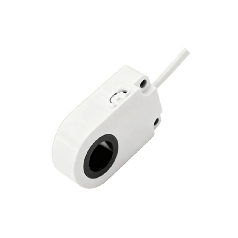
The choice of sensor technology can also influence resilience. Some sensor types are inherently more immune to certain environmental factors. For example, optical or fiber-optic sensors are immune to EMI, making them suitable for extreme electrical noise environments like near large motor drives or radio frequency (RF) transmitters. However, they may be sensitive to ambient light or physical bending. Conversely, robust current sensors based on the Hall effect or fluxgate principles are designed to operate in high-magnetic-field environments typical of power electronics.
Finally, system-level validation through rigorous testing under real-world operating conditions is non-negotiable. This includes testing for conducted and radiated emissions susceptibility, thermal cycling, and long-term stability. Data logging over extended periods can reveal intermittent issues that might not appear during brief bench tests.
In conclusion, integrating sensors near power sources is a complex but manageable task. Success hinges on a holistic approach that combines thoughtful physical design, intelligent circuit architecture, appropriate component selection, and thorough testing. By proactively addressing the intertwined issues of EMI, thermal effects, and power quality, engineers can unlock the benefits of close-proximity sensing without compromising on the integrity and reliability of the data collected.