The integration of laser sensors into Computer-Aided Design (CAD) environments represents a critical convergence of measurement technology and digital modeling. This synergy is fundamentally transforming workflows across manufacturing, robotics, quality control, and research & development. At its core, laser sensor CAD integration involves the use of precise, non-contact measurement data to inform, validate, and optimize virtual designs and simulations. This process closes the loop between the physical world and the digital twin, ensuring that theoretical models accurately reflect real-world conditions and constraints.
The primary function of a laser sensor within a CAD context is to capture high-fidelity geometric data. Sensors utilizing time-of-flight, triangulation, or interferometry principles generate dense point clouds of an object's surface. This raw data, representing millions of individual coordinate points, is then processed and imported into CAD software. Specialized modules or dedicated software packages facilitate this import, often converting the point cloud into a recognizable format such as a mesh or a Non-Uniform Rational B-Spline (NURBS) surface. This digital replica becomes a foundational reference for numerous engineering activities.
One of the most powerful applications is reverse engineering. Designers can scan an existing physical part—whether a legacy component without drawings or a hand-sculpted prototype—and instantly create an editable CAD model. This model can then be modified, optimized for manufacturing, or used to design mating components with perfect fit. It dramatically accelerates the product development cycle and preserves design knowledge from physical artifacts.
In quality assurance and inspection, CAD integration is indispensable. The as-designed CAD model serves as the nominal reference. Laser scanning captures the as-built condition of a manufactured part. Advanced inspection software then performs a comparative analysis, overlaying the point cloud data onto the original CAD geometry. The software generates color-coded deviation maps, visually highlighting areas where the manufactured part exceeds specified tolerances. This provides immediate, actionable feedback for production teams, enabling rapid correction and ensuring consistent quality without the need for complex physical fixtures like coordinate measuring machine (CME) programs in every case.
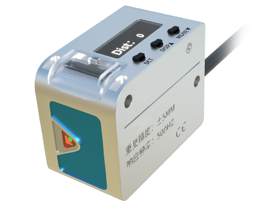
For simulation and analysis, such as Finite Element Analysis (FEA) or Computational Fluid Dynamics (CFD), the accuracy of the input geometry is paramount. Using idealized CAD models can sometimes lead to simulations that diverge from reality. By incorporating laser-scanned data of actual components—including inherent manufacturing variances, wear, or deformation—engineers can create simulation models that predict performance with far greater accuracy. This is crucial in fields like aerospace and automotive engineering, where marginal gains in predictive reliability translate to significant safety and performance benefits.
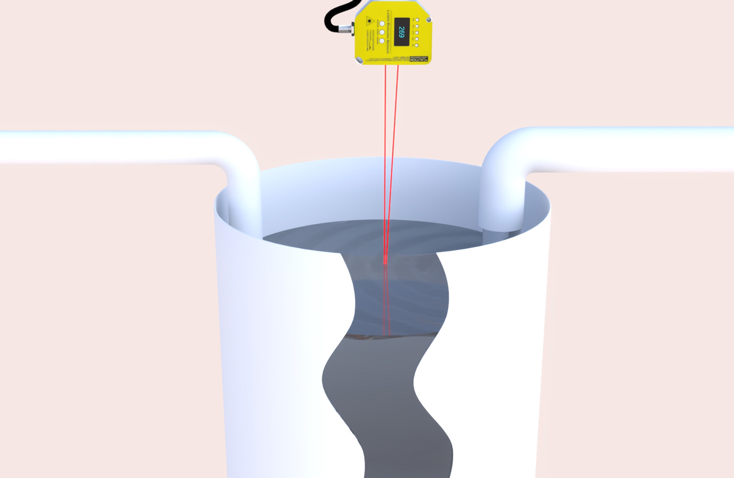
The workflow typically follows several key stages. First, strategic planning of the scan is essential, considering sensor resolution, field of view, and accessibility to all part features. Data acquisition follows, where the laser sensor systematically captures the object's geometry. Post-processing then cleans the raw point cloud, removing noise and outliers, and aligns multiple scans into a unified coordinate system. Finally, the processed data is imported into the CAD platform. Here, engineers may use automated surfacing tools to create parametric features or use the scan data as a precise reference canvas for new design work.
Choosing the right laser sensor and software is critical. Factors include measurement range, accuracy (often in microns), scanning speed, and the material/ surface finish of the target object. Software compatibility is equally important; the ecosystem must support seamless data flow from sensor to CAD, with robust tools for alignment, comparison, and modeling. Leading CAD platforms now offer native point cloud support or tightly integrated third-party plugins to streamline this pipeline.
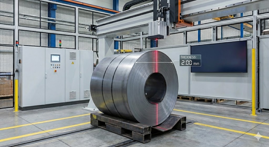
Looking forward, the trend is toward even tighter real-time integration. The rise of in-process monitoring sees laser sensors mounted on machine tools or robotic arms, providing live feedback directly into the CAD/CAM environment. This enables adaptive machining and real-time quality control, where the digital model is continuously updated based on sensor input, creating a truly dynamic and responsive manufacturing process. Furthermore, the integration with Augmented Reality (AR) overlays allows technicians to see deviation analyses or assembly instructions directly in their field of view, guided by the synergy of sensor data and CAD models.
In conclusion, laser sensor CAD integration is not merely a technical tool but a foundational methodology for modern precision engineering. It bridges the gap between design intent and physical reality, enabling faster innovation, guaranteed quality, and more reliable simulations. As sensor technology becomes more accessible and software more intelligent, this integrated approach will become the standard, empowering engineers to design and build with unprecedented confidence and accuracy.