Learning how to draw a proximity sensor is a valuable skill for students, engineers, and hobbyists involved in electronics, robotics, or technical illustration. This guide provides a clear, step-by-step approach to creating a simple yet accurate schematic diagram of a common inductive proximity sensor, focusing on clarity and standard conventions.
Before starting, gather your materials: paper, a pencil, an eraser, a ruler, and optionally, fine-line pens or drawing software for a digital finish. Understanding the basic function is helpful. A proximity sensor detects the presence or absence of a nearby object without physical contact, often represented in diagrams by its key internal and external components.
Step 1: Draw the Housing Outline
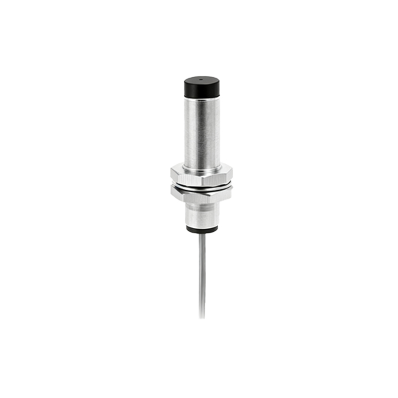
Begin by sketching the main body. For a typical cylindrical barrel sensor, draw a horizontal rectangle. This represents the side view. Keep the lines light and straight using your ruler. The rectangle's length should be roughly twice its height, mimicking common industrial sensor proportions.
Step 2: Add the Sensing Face
At the left end of the rectangle, draw a smaller, semi-circular shape to form the sensing face. This is the active area from which the detection field emanates. Connect it smoothly to the main housing. This distinct shape immediately identifies the drawing as a sensor.
Step 3: Illustrate Internal Components
Inside the housing rectangle, sketch the core functional symbols. Draw a coil symbol near the sensing face—this represents the inductive oscillator coil. It can be depicted as a series of three or four concentric semicircles. To its right, draw a small rectangle or triangle to symbolize the integrated circuit or processing unit. Connect these two elements with a simple straight line. Finally, add two parallel lines running from the circuit block to the right end of the housing; these represent the power and output wires.
Step 4: Detail the Wiring and Connections
At the right end of the housing, extend the two parallel lines outward. These are the sensor's leads or cable. Standard convention uses three wires for many sensors: Brown (+V), Blue (0V/GND), and Black (Output). For simplicity in a basic drawing, two lines are acceptable. You can label them near the connection point: +V, GND, and OUT. Use clear, printed text.
Step 5: Depict the Detection Field and Object
To show the sensor in operation, draw a series of dashed arcs emanating from the sensing face. This indicates the non-contact detection field. In front of the sensor, sketch a simple geometric shape, like a small square or rectangle, to represent the target metal object. Draw a double-headed arrow between the object and the sensing face, labeling it with "Detection Range" or a specific distance like "5mm".
Step 6: Finalize with Labels and Annotations
A good technical drawing is informative. Use a ruler to draw thin leader lines to each major part. Print the labels clearly: "Sensing Face", "Oscillator Coil", "Processing Circuit", "Cable/Connector", "Target Object", and "Detection Field". Add a title below your drawing: "Schematic Diagram of an Inductive Proximity Sensor". Ink over your final pencil lines for permanence and erase any construction guidelines.
Tips for Accuracy and Clarity:
Consistency is Key: Maintain uniform line weights. Use thick lines for the outer housing and thin lines for internal details and leader lines.
Use Symbols: Familiarize yourself with standard electrical and electronic symbols. The coil symbol is universally recognized.
Digital Tools: For repeated or professional use, consider using free diagramming software like draw.io or KiCad's schematic editor. These tools have libraries of standardized symbols.
Context Matters: If drawing for a specific circuit diagram, include the sensor's connection to a power supply (like a 24V DC symbol) and a load (like a PLC input or a relay coil).
Practice this sequence several times. Start with the basic housing and sensing face, then gradually add internal details. The goal is not artistic perfection but communicative clarity. A well-drawn proximity sensor diagram effectively conveys function and connections, aiding in project planning, documentation, and educational explanations. Remember, the best technical drawings are simple, labeled, and adhere to common engineering conventions, making them understandable to a wide audience.