Proximity sensors are fundamental components in modern industrial automation, providing non-contact detection of objects. Their programming and integration into control systems are critical for efficient machine operation. This article presents practical programming examples using common industrial controllers and sensors, focusing on real-world applications.
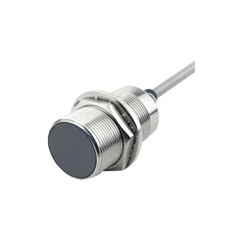
A common application is object counting on a conveyor belt. Using a cylindrical inductive proximity sensor (e.g., sensing range 8mm) connected to a PLC (Programmable Logic Controller) like a Siemens S7-1200, the logic is straightforward. The sensor's normally open (NO) digital output is wired to a PLC digital input (e.g., I0.0). The primary programming task involves using a positive edge detection instruction. In Ladder Logic (LAD), a typical network would use a normally open contact for the input (I0.0) to trigger a positive edge detection bit (e.g., M0.0). This edge bit then increments a counter function (e.g., "CTU" up counter). This ensures each passing object is counted only once, even if the sensor remains activated as the object passes. The counter's preset value can be used to trigger an output, such as activating a diverter gate after 10 units.
For more precise positioning, such as in a rotary indexing table, capacitive or ultrasonic sensors might be used. Here, programming focuses on state sequencing. The sensor detects the presence of a workpiece in the "load station." The PLC program uses this input to enable a pneumatic actuator or robot only when the part is confirmed present and the station is in the correct position (verified by a separate rotary encoder). This is often implemented using a sequential function chart (SFC) or a state machine in structured text (ST). For instance, the transition from an "Idle" state to a "Load" state is conditioned by the proximity sensor being TRUE AND other safety interlocks.
Analog proximity sensors, which provide a continuous voltage or current signal proportional to distance, require different handling. A typical 4-20mA analog sensor measuring fill level in a hopper would be connected to a PLC's analog input module. Programming involves scaling the raw analog value (e.g., 0-27648 for a 4-20mA signal) into engineering units (e.g., 0-1000 mm). In a PLC like Allen-Bradley's ControlLogix, this is done with the Scale (SCL) instruction. The scaled value can then be used in comparison logic. For example, if the level falls below 200mm (Low-Level), the PLC opens a feed valve. If it rises above 900mm (High-Level), the valve closes. This creates a simple control loop managed entirely by the PLC logic.
Safety-critical applications, like light curtains or safety-rated laser scanners, involve specialized safety PLCs (e.g., Siemens Safety Integrated). Programming these is done in dedicated safety languages like F-LAD (Function Block Diagram for Safety). A basic example is an area guard on a robotic cell. The safety sensor's OSSD (Output Signal Switching Device) outputs are wired to safety input terminals. The logic is simple but certified: if the sensor's guarded zone is breached (input goes FALSE), the safety program immediately sets a safe torque off (STO) signal to the robot drive, halting motion. This logic must be tested and validated according to relevant standards (e.g., ISO 13849).
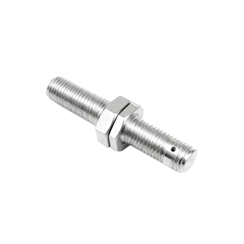
Integrating a sensor with a microcontroller like an Arduino offers a low-cost prototyping example. Connecting a common 3-wire NPN inductive sensor (e.g., LJ12A3-4-Z/BX) involves connecting its output pin to a digital input pin on the Arduino. The sensor's output is low (0V) when active. A simple Arduino sketch reads this pin using digitalRead(). The code can then perform an action, such as turning on an LED or sending a serial message. Debouncing in software (adding a short delay after detection) is often necessary to ensure a single, clean signal per object.
Debugging is a crucial part of programming. Most industrial software includes force and monitor functions. A programmer can monitor the sensor's input bit in real-time to verify it toggles when an object is present. If it doesn't, the issue could be wiring, sensor alignment, or the sensing object's material. For analog sensors, trending the scaled value on an HMI (Human-Machine Interface) graph is essential for tuning thresholds and verifying linearity.
Best practices include always implementing sensor diagnostics. For instance, a program can include a timer that triggers an alarm if a sensor expected to cycle regularly (like on a packaging machine) remains inactive for an abnormally long period, indicating a possible jam or sensor failure. Using shielded cables, proper grounding, and maintaining adequate clearance from other metal objects are vital hardware considerations that