Glass proximity sensors have become integral components in modern electronic devices, enabling touchless interactions, screen management, and power conservation. Found in smartphones, tablets, kiosks, and automotive displays, these sensors detect the presence of nearby objects, typically a user's face or hand, without physical contact. Ensuring they function correctly is crucial for device reliability and user experience. This guide outlines practical methods for testing a glass proximity sensor, helping technicians, engineers, and enthusiasts verify performance and diagnose common issues.
The fundamental principle behind a glass proximity sensor involves an infrared (IR) light-emitting diode (LED) and an IR photodetector. The IR LED emits an invisible light beam through the glass. When an object approaches, the light reflects back to the photodetector, which converts the signal for the device's processor. Testing, therefore, focuses on the integrity of this optical pathway and the electronic response.
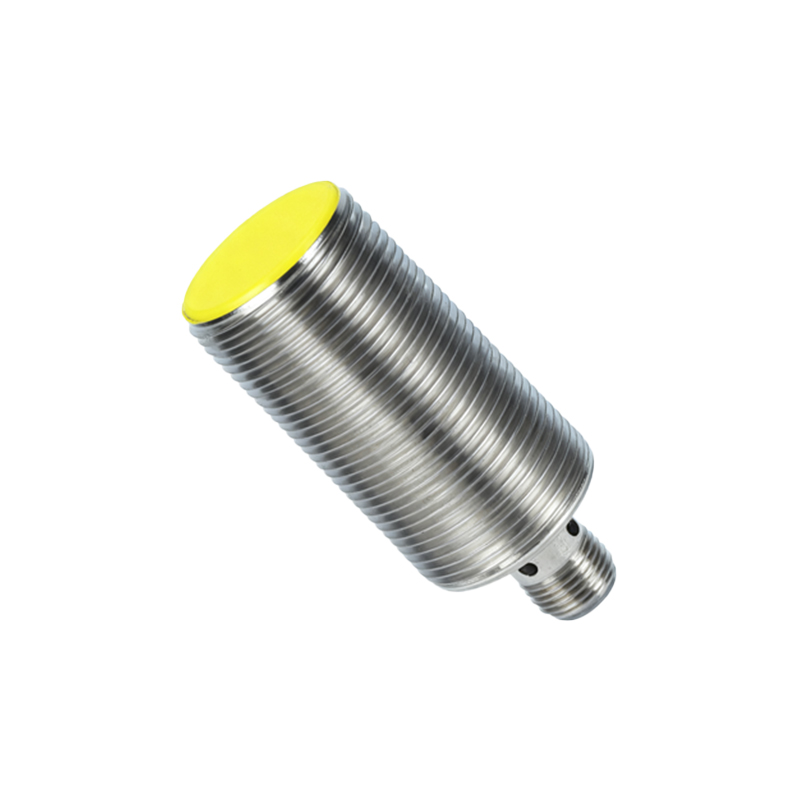
A systematic testing approach begins with a visual inspection. Examine the sensor area on the glass for any cracks, deep scratches, or obstructions like dirt, dust, or adhesive residue. Even minor imperfections on the glass surface can scatter or block IR light, leading to erratic behavior. Clean the glass thoroughly with a lint-free cloth and isopropyl alcohol to ensure a clear optical path.
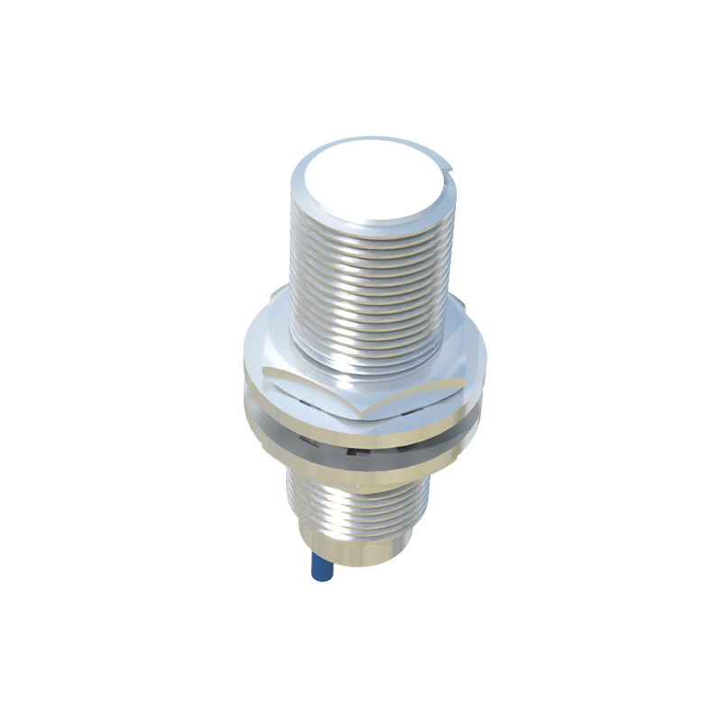
Next, verify the basic electronic functionality. Using a digital multimeter, you can perform preliminary checks. With the device powered off, set the multimeter to diode test mode. Place the probes on the sensor's IR LED terminals (consult the device schematic for polarity). A functioning LED will typically show a forward voltage drop between 1.2V and 1.8V. An open circuit reading indicates a burnt-out LED. For the photodetector, resistance mode can sometimes be used; expect a high resistance that decreases slightly when strong IR light is shined directly on it. However, this is a basic check and doesn't replicate real-world conditions.
The most effective test simulates actual operation. For this, you need to power the sensor circuit. If testing within the assembled device, you can often access diagnostic modes or use third-party applications that display real-time sensor data. For example, on Android devices, entering#0# in the dialer often opens a hardware test menu with a proximity sensor test option. The app will usually show a value that changes when you bring your hand close. A value that toggles between "FAR" and "NEAR" confirms basic operation.
For bench testing a standalone sensor module, a simple Arduino or Raspberry Pi setup is invaluable. Connect the sensor's VCC, GND, and output signal pin to the microcontroller. Write a basic script to read the digital or analog output from the sensor. Observe the output readings while moving a standard reflective object (like a white card) toward and away from the sensor at the specified detection distance. The output should change state predictably. You can log the data to identify inconsistencies, such as a failure to detect at the correct range or intermittent triggering.
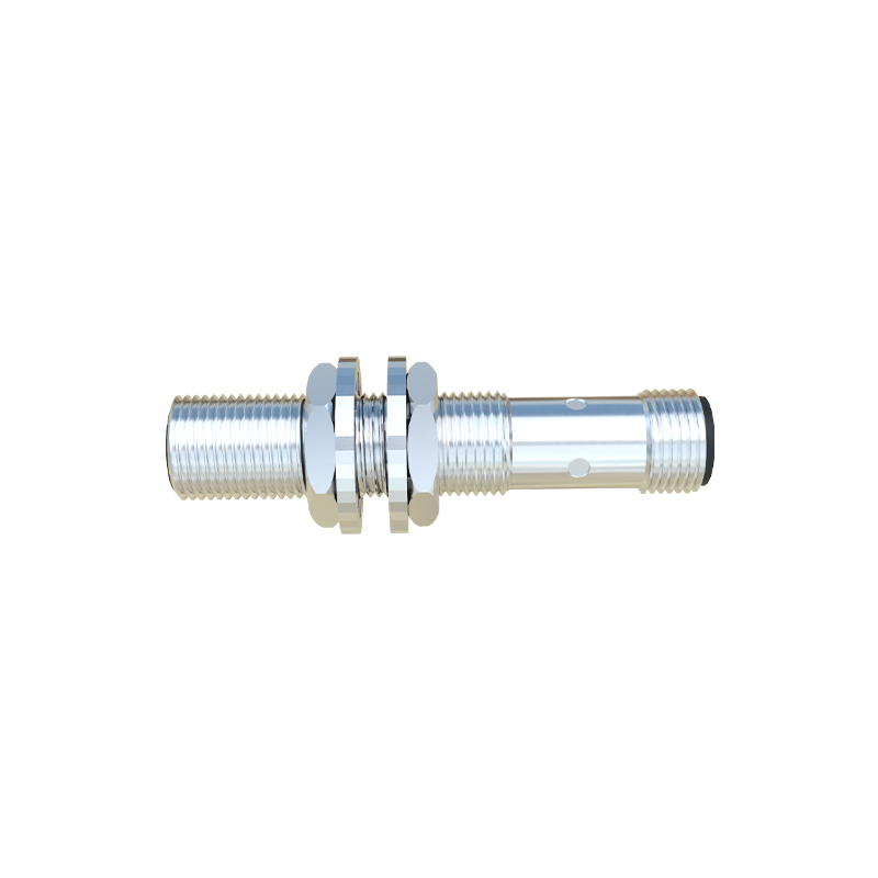
Calibration is a critical aspect often overlooked in testing. Many proximity sensors require software calibration to set the baseline for "far" and "near" thresholds. A test might pass basic functionality but fail in the device due to poor calibration. If possible, run the manufacturer's official calibration routine using service software. Symptoms of poor calibration include the screen turning off during a call before the phone reaches your ear or failing to turn back on when moved away.
Common failure modes to identify during testing include constant triggering (stuck in "NEAR" state), no triggering (stuck in "FAR" state), and inconsistent detection range. Constant triggering can be caused by contamination on the glass creating permanent reflection, a faulty photodetector, or a short circuit. No triggering often points to a dead IR LED, a damaged photodetector, or a broken connection. Inconsistent range is frequently due to weak LED output, degraded photodetector sensitivity, or improper calibration.
Environmental testing adds another layer of rigor. Sensor performance can vary with ambient light. Test under different lighting conditions—bright sunlight, darkness, and under fluorescent or LED lights—to ensure the sensor isn't falsely triggered by environmental IR noise. Some sensors have optical filters to mitigate this, but they can degrade.
Finally, document your test parameters and results. Note the test distance, object used, ambient conditions, and output values. This documentation is essential for quality control, troubleshooting recurring issues, and verifying repairs. For integrated devices, after any repair involving glass or sensor replacement, full functional testing followed by a calibration cycle is mandatory before considering the job complete.
By following these steps—visual inspection, electronic verification, operational simulation, calibration check, and environmental assessment—you can comprehensively evaluate the health of a glass proximity sensor. This process ensures the sensor meets its design specifications, providing the seamless, intuitive interaction