Building your own laser displacement sensor is an exciting project that combines optics, electronics, and programming. This guide walks through a functional, low-cost design suitable for hobbyists, makers, and students interested in precision measurement. Unlike complex industrial systems, this DIY approach focuses on accessible components and clear principles.
A laser displacement sensor typically works on the triangulation principle. A laser diode projects a focused spot onto a target surface. The reflected light is captured by a lens and focused onto a position-sensitive detector, such as a linear CCD or a PSD (Position Sensitive Device). As the target distance changes, the position of the reflected spot shifts on the detector. By calibrating this shift against known distances, you can calculate displacement with good accuracy.
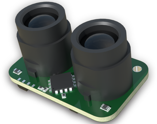
For the laser source, a common 650nm red laser diode module with a line-generating lens is ideal. It creates a sharp, thin line that improves detection consistency. The key optical component is the receiver. Many DIY builders use a linear CCD like the TCD1304AP, which is affordable and offers high pixel resolution. Alternatively, a simpler analog PSD can be used for faster response, though with potentially lower resolution. A focusing lens, such as a small convex lens, is mounted in front of the detector to image the reflected laser line.
The electronic core is a microcontroller. An Arduino Uno or similar board is perfect for handling data acquisition and initial processing. The linear CCD requires precise timing signals for pixel readout, which the Arduino can generate via its digital pins. The analog voltage output from the CCD is read by the Arduino's analog-to-digital converter. For a PSD, the output is usually analog currents that need a transimpedance amplifier circuit to convert to measurable voltages.
Assembly starts with mechanically fixing the laser emitter and the receiver lens at a known angle, typically between 20 to 45 degrees. This baseline distance and angle are critical for triangulation math. Enclose the components in a rigid, light-blocking housing to minimize ambient light interference. Small apertures on the housing help define the optical path.
The software involves two main parts: data acquisition and calibration. The code reads the pixel array from the CCD, finds the brightest spot's centroid position using a simple algorithm, and maps this pixel position to a physical distance. Calibration is the most crucial step. Place a flat target at precisely known distances (using a caliper or gauge blocks) and record the corresponding centroid pixel values. Plotting these points creates a calibration curve, which can be fitted with a polynomial equation. This equation is then embedded in the code to convert future readings into real-world distances.
Performance depends heavily on careful calibration and stable mounting. Typical DIY sensors can achieve sub-millimeter accuracy in a range of a few centimeters. Surface properties affect results; dark or shiny surfaces may require gain adjustment or different laser power. Adding temperature stability for the laser or using a reference light source can improve long-term reliability.
Applications for a homemade sensor are vast: 3D scanner profiling, vibration measurement on small machines, liquid level sensing, or as a teaching tool for mechatronics. It offers a deep, practical understanding of optoelectronic sensing far beyond textbook theory.
Remember, laser safety is paramount. Always use low-power laser modules (Class 2 or below), avoid direct eye exposure, and clearly label your device. With patience and meticulous calibration, you can create a capable measurement tool that opens doors to advanced projects in robotics and automation. The total cost can be under $50, making it a rewarding investment in hands-on engineering skills.