Proximity sensors are ubiquitous in modern industrial automation, consumer electronics, and automotive systems. Their primary function is to detect the presence or absence of an object within a specific range without physical contact. Ensuring these sensors operate correctly is critical for system reliability, safety, and efficiency. This guide outlines practical, hands-on methods for testing various types of proximity sensors, moving beyond theoretical specifications to real-world validation.
The first step in any testing procedure is to understand the sensor type. Inductive proximity sensors detect metallic objects, capacitive sensors detect both metallic and non-metallic materials, and photoelectric sensors use light beams. Ultrasonic sensors employ sound waves, while Hall Effect sensors respond to magnetic fields. Each type requires a slightly different testing approach, though the core principles of verifying detection range, repeatability, and output signal integrity remain constant.
A fundamental test is the verification of the sensing distance, often called the "operating distance" or "Sn." This is not the maximum range at which a sensor might sporadically trigger, but the guaranteed reliable detection distance under standardized conditions. To test this, use a standard target specified by the sensor's datasheet—typically a square of mild steel (Fe 360) for inductive sensors. Mount the sensor securely. Gradually move the target toward the sensor's active face along the axis of sensitivity. Mark the point where the output consistently switches state (e.g., from OFF to ON). Measure this distance. It should fall within the nominal operating distance (Sn) tolerance, usually ±10%. Repeat this process several times to check for hysteresis, the difference between the switch-on and switch-off points.
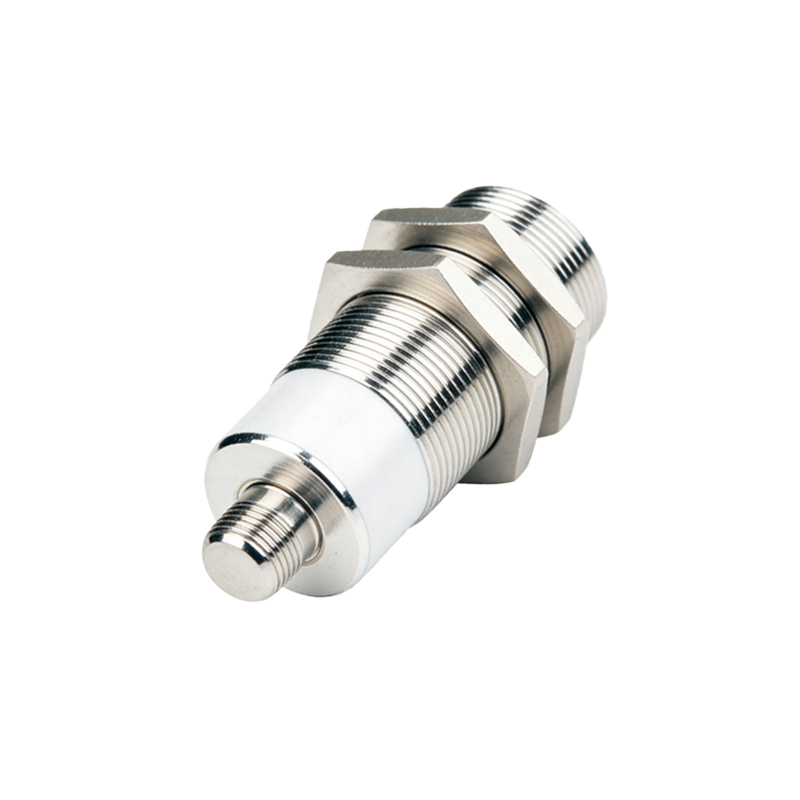
Next, assess the sensor's repeatability. This is its ability to consistently detect the target at the same distance. Perform the sensing distance test multiple times (e.g., 50-100 cycles). The variation in the switch point should be minimal, typically less than 5% of Sn. Inconsistent readings can indicate a faulty sensor, unstable power supply, or electrical interference.
Output signal testing is crucial. Connect the sensor to its intended load (e.g., a PLC input, relay, or indicator lamp) or a suitable test instrument like an oscilloscope or a digital multimeter. For a digital (discrete) sensor, observe the voltage level in the ON and OFF states. A sinking (NPN) sensor should pull the signal line close to 0V when active, while a sourcing (PNP) sensor should pull it close to the supply voltage (e.g., 24V). Ensure the voltage drop in the ON state is within acceptable limits to reliably drive the load. For analog output sensors (4-20mA, 0-10V), measure the output signal at minimum and maximum sensing conditions. Check for linearity by taking measurements at several intermediate points. The output should change smoothly and proportionally to the target distance without significant steps or noise.
Environmental testing simulates real-world conditions. Check for the influence of temperature by operating the sensor at the extremes of its rated range. Note any drift in the sensing point. For sensors used in washdown or outdoor applications, verify ingress protection (IP rating) is adequate, though this is often a design selection check rather than a routine test. A key test for inductive sensors is checking their immunity to non-target metals. Bring different types of metal (aluminum, copper, stainless steel) near the sensor. The sensing distance will vary significantly from mild steel; this is normal behavior but must be documented. The sensor should not false-trigger due to adjacent machinery or electrical noise. Observe its operation while nearby motors start/stop or welders operate.
For photoelectric sensors, clean the lens and reflector. Test the alignment of through-beam sensors. For diffuse reflective types, test with the specified color and surface finish, as these greatly affect performance. Check for the effects of ambient light. For ultrasonic sensors, ensure the target surface is adequate for sound wave reflection and test for interference from air currents or acoustic noise.
A simple functional test involves a "go/no-go" fixture. Set a target at the required operational distance. The sensor should reliably detect it every time. Move the target just outside the required range; the sensor should not detect it. This quick test is ideal for production line checks or field maintenance.
Always prioritize safety. Disconnect power before wiring. Follow lock-out/tag-out procedures in industrial settings. Use the manufacturer's datasheet as the primary reference for test parameters, electrical connections, and performance specifications. Document all test results, including conditions and any deviations from expected behavior. Regular testing and calibration, as part of a preventive maintenance schedule, prevent unexpected downtime and ensure the long-term, reliable operation of systems dependent on proximity sensing technology.