Laser sensor modules have become indispensable tools across various industries, from robotics and automation to security systems and consumer electronics. Understanding their proper usage is crucial for achieving accurate measurements, reliable operation, and ensuring safety. This guide provides a detailed, step-by-step approach to effectively using a laser sensor module.
First and foremost, safety is paramount. Always treat a laser module with respect. Before powering the device, carefully read the manufacturer's datasheet to identify its laser class (typically Class 1, 2, or 3R for common modules). Never look directly into the laser beam or point it at reflective surfaces that could deflect the light into someone's eyes. Use appropriate laser safety goggles if working with higher-power modules. Ensure the work area is clean and organized to prevent accidental exposure.
The initial setup involves hardware connections. A typical laser sensor module has three to five pins: VCC (power supply), GND (ground), and a signal output pin (often labeled OUT, SIG, or analog/digital specific). Some advanced modules may have additional pins for configuration or different output modes. Connect the VCC pin to a stable power source matching the module's voltage requirement (commonly 3.3V or 5V DC). Connect the GND pin to the common ground of your power source and microcontroller (like an Arduino, Raspberry Pi, or ESP32). The signal pin is connected to a digital or analog input pin on your controller, depending on the module's output type.
Power sequencing is important. Apply power to the module only after all connections are double-checked. A stable power supply is critical; voltage spikes or noise can damage the sensitive laser diode. Using a decoupling capacitor (e.g., 100µF) close to the module's VCC pin is a good practice to smooth out power fluctuations. Upon power-up, a small indicator LED on the module might illuminate, signaling it is active.
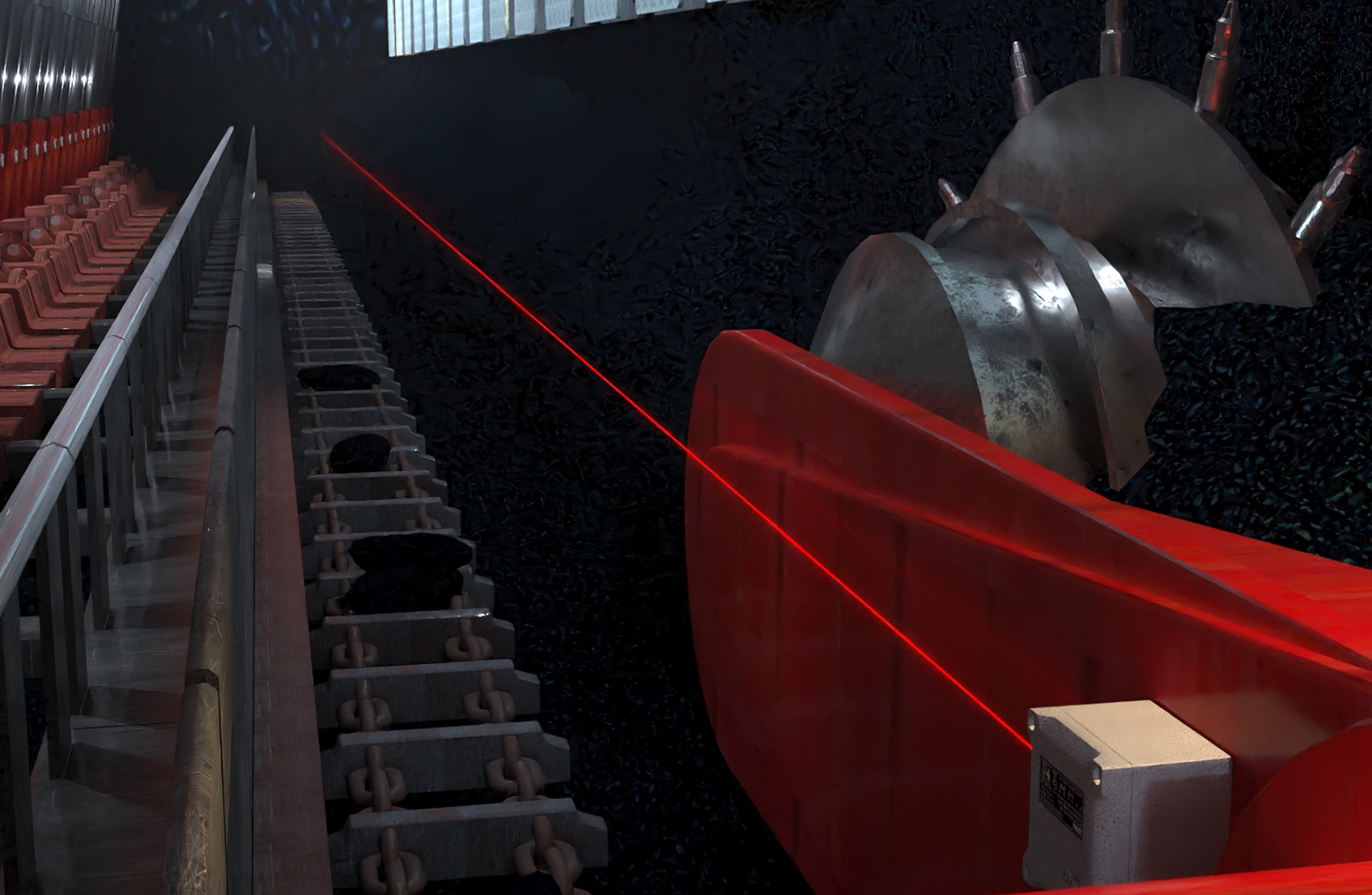
Understanding the output type is the next critical step. Modules generally provide either a digital or analog output. A digital output provides a simple HIGH/LOW signal. For example, in a laser tripwire security system, the output might go LOW when the beam is interrupted. An analog output provides a voltage that varies proportionally with the received signal strength, commonly used in distance measurement or surface reflectivity sensing. Consult your module's datasheet to interpret the output correctly.
Calibration and testing come after the basic electrical setup. For distance-measuring modules (like time-of-flight sensors), calibration often involves placing a target at a known distance and adjusting code parameters or potentiometers on the board (if available) to match the reading. For simple presence detection, test by breaking the beam and observing the output signal change on your microcontroller's serial monitor or via an LED. Environmental factors like ambient light, dust, or the target's color and texture can affect performance. Testing under real-world conditions is essential.
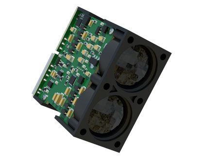
Integrating the module with code is straightforward. For a digital module, you would use a function likedigitalRead() on an Arduino to check the pin state. For an analog module,analogRead() captures a value between 0 and 1023 (on a 10-bit ADC), which you then map to a physical quantity like distance or intensity. Here is a basic Arduino example for a digital laser receiver module:
``cpp
const int laserPin = 7; // Digital input pin
void setup() {
Serial.begin(9600);
pinMode(laserPin, INPUT);
}
void loop() {
int sensorState = digitalRead(laserPin);
if (sensorState == LOW) { // Beam interrupted
Serial.println("Beam Broken!");
// Trigger an alarm, stop a motor, etc.
}
delay(100); // Short delay for stability
}
``
For analog sensors, the code would involve reading the analog value and potentially applying a formula from the datasheet to convert it to centimeters or millimeters.
Practical applications dictate specific usage nuances. In robotics, for line following or obstacle avoidance, the module must be mounted securely to minimize vibration, which can cause noisy signals. In industrial counting or alignment systems, ensuring the beam is perpendicular to the target surface improves accuracy. For communication applications (like laser data transmission), precise alignment between the transmitter and receiver is critical, and modulation techniques are used in the code.
Finally, consider long-term maintenance and troubleshooting. Keep the laser lens clean from dust and fingerprints using a soft, lint-free cloth. Check connections periodically for corrosion or looseness. If readings become erratic, verify the power supply voltage and test in a dark environment to rule out ambient light interference. Always store the module in a protective case when not in use.
By following these steps—prioritizing safety, making correct connections, understanding the output, calibrating for your environment, writing appropriate code, and considering application-specific mounting—you can reliably integrate a laser sensor module into your projects. These devices offer high precision and versatility, making them powerful components in the toolkit of any engineer, hobbyist, or developer.