Introduction to Photoelectric Sensors in Lift Platforms
Photoelectric sensors are critical components in modern lift platforms, ensuring precise positioning, safety interlocks, and load detection. As an electrical engineer, understanding the schematic diagram of these sensors is essential for troubleshooting, design, and integration. This article delves into the core principles, circuit components, and signal processing involved in a typical photoelectric sensor system for lift platforms, focusing on through-beam, retro-reflective, and diffuse sensor configurations.
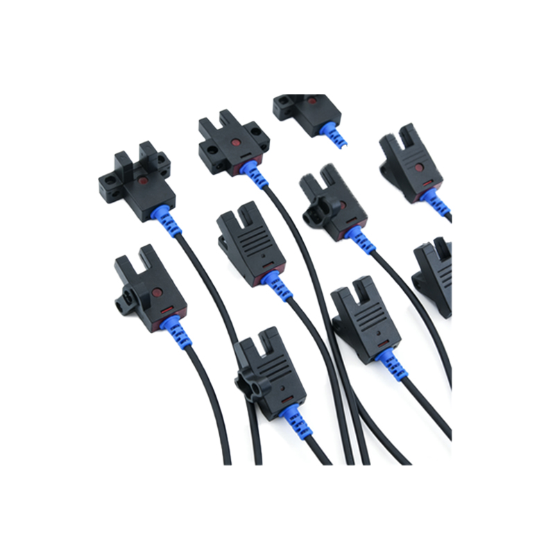
Basic Operating Principle of Photoelectric Sensors
The operating principle relies on the interruption or reflection of a light beam, typically using infrared (IR) or visible red LED sources. A photoelectric sensor consists of an emitter (LED) and a receiver (phototransistor or photodiode). In a lift platform context, the sensor detects the presence or absence of an object, such as a platform edge or a load, by monitoring changes in light intensity. The circuit diagram includes a power supply (commonly 12-24V DC), a switching amplifier, and an output transistor (NPN or PNP) that interfaces with a PLC or relay logic.
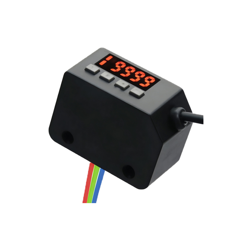
Key Components in the Sensor Circuit Diagram
A typical schematic includes: (1) Power regulation stage: A voltage regulator (e.g., LM7805) stabilizes the input supply to 5V for the emitter and receiver circuits. (2) Emitter circuit: A current-limiting resistor (e.g., 220 ohms) in series with the IR LED ensures safe operation. (3) Receiver circuit: A phototransistor (e.g., BPW96C) is biased with a collector resistor (10k ohms) to produce a voltage signal proportional to light intensity. (4) Signal conditioning: An operational amplifier (e.g., LM393) configured as a comparator compares the receiver voltage to a reference voltage set by a potentiometer, providing hysteresis to avoid noise-induced false triggers. (5) Output stage: An NPN transistor (e.g., 2N2222) drives the output, which can be open-collector or push-pull depending on the platform requirements.
Circuit Diagram Analysis for Lift Platform Applications
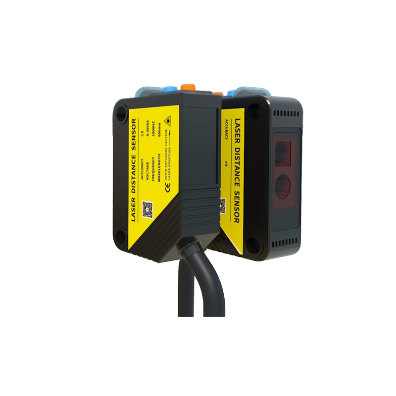
For a lift platform, the sensor circuit must handle vibration, dust, and varying ambient light. The schematic often includes a low-pass filter (RC network with R=10k, C=0.1uF) on the comparator output to debounce the signal. In a through-beam configuration, the emitter and receiver are separate modules; the circuit detects the object when the beam is broken. In a retro-reflective setup, a reflector is used, and the sensor output changes when the reflected beam is interrupted. The diagram should also incorporate an LED indicator (e.g., red for unblocked, green for blocked) driven by a transistor (e.g., BC547) for visual diagnostics.
Signal Processing and Output Interface
The comparator output (from LM393) is fed into a microcontroller (e.g., Arduino or PLC) via a level shifter if the sensor operates at 5V and the controller uses 3.3V logic. Alternatively, a transistor can directly drive a relay (e.g., SRD-05VDC-SL-C) for heavy-duty loads. The schematic should include a flyback diode (1N4007) across the relay coil to protect against voltage spikes. Engineers must also consider cable length: for distances over 10 meters, twisted-pair shielded cables and a differential line driver (e.g., DS26LS31) are recommended to maintain signal integrity.
Common Troubleshooting and Design Considerations
When analyzing the circuit diagram for a lift platform sensor, common issues include: (1) False triggering due to ambient light—solved by adding IR filters or modulating the LED at a specific frequency (e.g., 38 kHz). (2) Voltage drop over long cables—use a separate power supply with decoupling capacitors (100uF + 0.1uF) at the sensor end. (3) Thermal drift—select components with low-temperature coefficients (e.g., metal-film resistors) and ensure adequate ventilation. The schematic should also include a test point (e.g., TP1 at the comparator output) for oscilloscope probing during commissioning.
Conclusion and Best Practices
A well-designed photoelectric sensor circuit diagram for lift platforms prioritizes reliability, noise immunity, and ease of maintenance. Use standard logic levels (5V or 24V) and modular connectors (e.g., M12) for field replacement. Always include polarity protection (a diode at the power input) and ESD protection (TVS diodes at the output). By mastering these circuit details, electrical engineers can ensure safe and efficient operation of lift platform systems in industrial automation.