Proximity sensors are ubiquitous in modern industrial automation, robotics, and consumer electronics, providing non-contact detection of objects. Their reliability is paramount for system uptime and safety. However, like any electronic component, they are susceptible to failure. A systematic approach to failure analysis is crucial for minimizing downtime and implementing effective corrective actions. This guide delves into the common failure modes, root causes, and practical troubleshooting steps for inductive, capacitive, and photoelectric proximity sensors.
The first step in any analysis is recognizing the symptoms of a failing sensor. Common indicators include intermittent operation, where the sensor output flickers or drops out unpredictably. A complete failure to detect any target within its specified sensing range is another clear sign. Conversely, a sensor might exhibit constant activation, remaining "on" even when no target is present. Reduced sensing range, where the sensor only detects objects at a distance significantly shorter than its rated specification, is also a frequent complaint. Finally, physical damage to the housing, sensing face, or cable is an obvious, though not always the root, cause of malfunction.
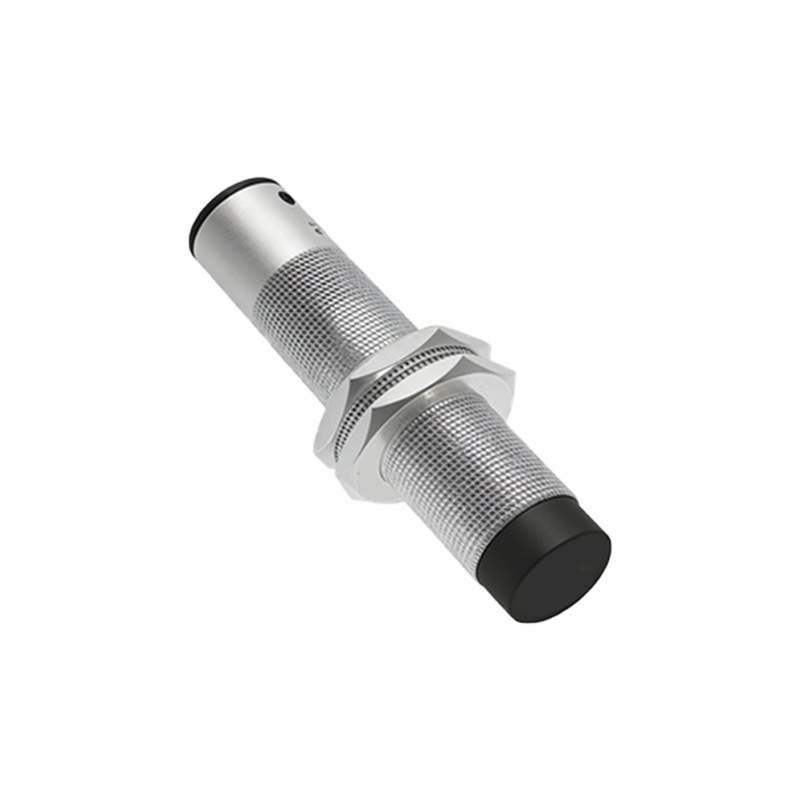
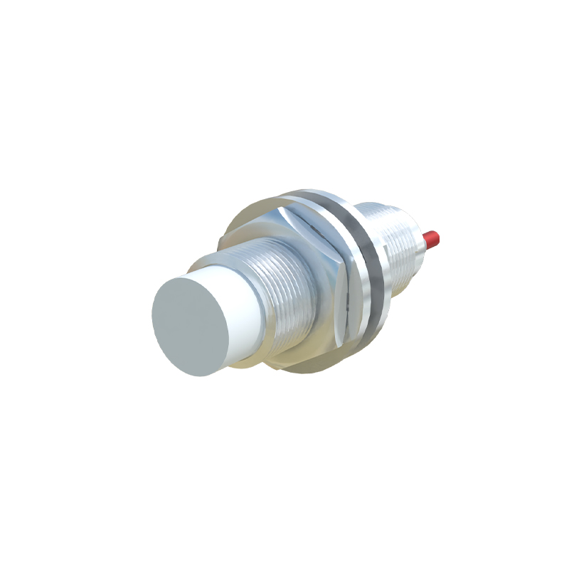
Understanding the internal technology is key to diagnosing issues. Inductive sensors, which detect metallic objects, can fail due to metal shavings or conductive dust accumulation on the sensing face, creating a false "target." Strong electromagnetic interference (EMI) from nearby motors, welders, or power lines can swamp the sensor's oscillator circuit, leading to erratic behavior. Internal component failure, such as a damaged oscillator coil or output transistor, is another possibility. For capacitive sensors, which react to a wider range of materials, environmental factors are critical. Changes in humidity, temperature, or the buildup of non-conductive contaminants (oil, dust) on the face can alter the dielectric constant and cause false triggering or loss of sensitivity. Incorrect installation near grounded metal surfaces can also create a parasitic capacitance effect.
Photoelectric sensors, using light beams, have a distinct set of vulnerabilities. Lens contamination is the primary enemy; dirt, oil, or condensation on the transmitter or receiver lens severely attenuates the light signal. Misalignment due to vibration or impact can break the beam path. Ambient light interference, particularly from powerful sources like sunlight or strobe lights operating at a similar frequency, can blind the receiver. Finally, LED degradation over time, though a slow process, can gradually reduce the effective sensing range.
A structured troubleshooting procedure begins with the simplest checks. First, verify the basics: ensure power is present and within the sensor's specified voltage range. Check all electrical connections for tightness and corrosion. Inspect the wiring for cuts, pinch points, or damage, especially at cable entry points. For photoelectric sensors, meticulously clean the lenses with an appropriate solvent. For inductive/capacitive types, clean the sensing face of any debris.
Next, evaluate the installation and environment. Confirm the sensor is correctly mounted with proper clearance from surrounding metal (as per datasheet). Assess the target itself: is it the correct size, material, and presented squarely to the sensor? Has anything in the environment changed? New machinery causing EMI or vibration? Changes in air quality introducing condensation or dust? Swapping the suspect sensor with a known-good unit from a similar application is a highly effective isolation test. If the problem follows the sensor, it is faulty. If it remains in the original location, the issue lies with the installation, wiring, or controller input.
For persistent electrical issues, use a multimeter to monitor the output. For a sinking (NPN) or sourcing (PNP) DC sensor, check if the output switch (transistor) is functioning correctly—switching fully to the supply voltage or ground. An oscilloscope can reveal noise on the power lines or output signal that a multimeter might average out. If EMI is suspected, try installing ferrite cores on the cable near the sensor or relocating the sensor or its wiring away from noise sources.
Preventive maintenance is the best strategy against failures. Implement regular cleaning schedules for sensor lenses and faces. Use protective accessories like baffles for photoelectrics or plastic face guards for inductive sensors in dirty environments. Ensure proper strain relief on cables to prevent wire breakage from constant flexing. Adhere to manufacturer specifications for operating temperature, voltage, and environmental protection (IP rating). Keeping a log of failures can help identify patterns and chronic issues in specific applications.
In conclusion, proximity sensor failures stem from electrical, environmental, mechanical, or application-specific causes. A methodical approach—starting with visual inspection, verifying power and connections, assessing environmental factors, and performing substitution tests—will efficiently diagnose most problems. Understanding the underlying sensing technology guides the investigator to the most likely culprits, enabling swift restoration of operation and informed improvements to prevent recurrence.