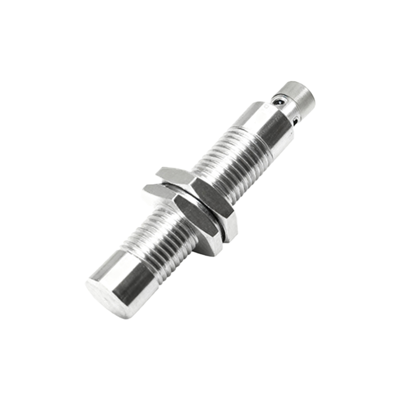
Proximity switch sensors are ubiquitous in industrial automation, robotics, and machinery. Their markings, often etched or printed on the housing, serve as a critical communication tool for installers, technicians, and engineers. Understanding these codes is not merely about compliance; it's about ensuring safety, optimizing performance, and simplifying troubleshooting. This guide deciphers the common symbols and alphanumeric codes found on these devices.
The most fundamental markings denote the sensor type. The primary distinction is between inductive (for detecting metals), capacitive (for detecting materials like liquids, wood, or plastics), and ultrasonic sensors. This is often indicated by a symbol. An inductive sensor might be marked with a coil icon or simply "IN," while a capacitive one could show a capacitor symbol or "CAP." The sensing distance, a crucial parameter, is always clearly stated, for example, "5mm" or "20mm." This is the nominal range under standardized conditions.
Wiring and electrical characteristics are heavily coded. Look for markings like "DC" or "AC" followed by voltage ranges (e.g., 10-30V DC). The output type is key: "PNP" or "NPN" for DC sensors, indicating the switching transistor type, and "NO" (Normally Open) or "NC" (Normally Closed) for the contact state. These are frequently represented with schematic diagrams. The international standard IEC 60947-5-2 defines many symbols for function and output. A square with a diamond inside often denotes a switching element, with lines indicating PNP or NPN configuration.
Protection ratings are communicated through IP (Ingress Protection) codes, such as IP67 or IP69K. IP67 signifies complete dust ingress protection and protection against temporary immersion in water. This is vital for choosing a sensor for washdown or outdoor environments. Additional safety certifications, like UL, CE, or CCC marks, indicate compliance with regional safety standards.
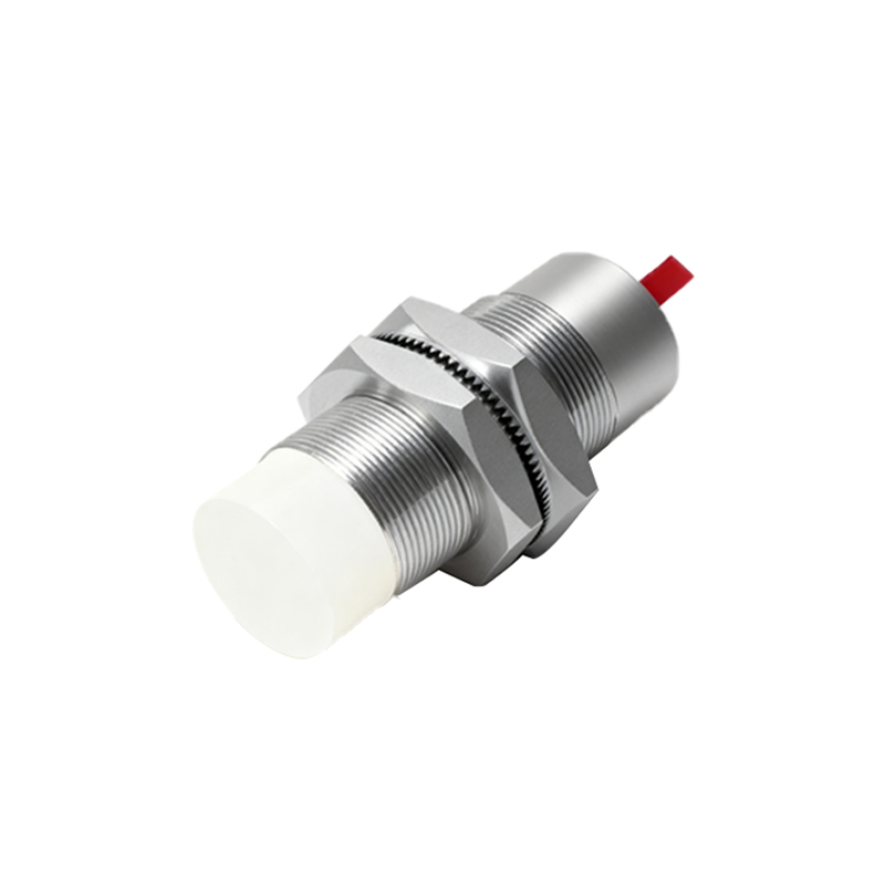
Housing material, like "BRASS" or "STAINLESS STEEL," may be marked, especially for inductive sensors where the face material affects performance. Some sensors include LED indicators, and their behavior (power on, output active, fault) might be explained with small icons. A series of numbers and letters, the part number or type code, is the gateway to the full datasheet. Searching this code online provides the complete technical specification.
Ignoring these markings can lead to incorrect installation, such as wiring an NPN sensor to a PNP PLC input, causing malfunctions or damage. Using an unshielded inductive sensor near metal when a shielded ("flush-mountable") type is required reduces its effective sensing range. Misinterpreting the protection rating can lead to premature sensor failure in harsh conditions.
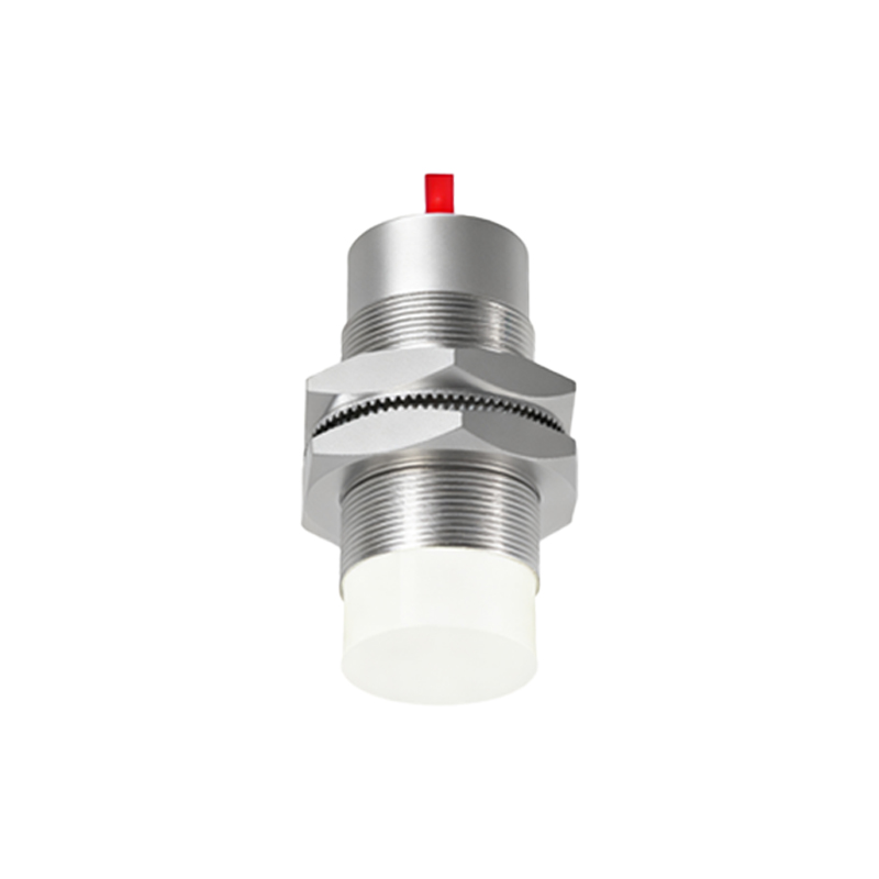
In summary, the markings on a proximity sensor form a concise technical language. Taking time to read and understand them—referring to the manufacturer's datasheet when in doubt—is an essential practice. It ensures the right sensor is selected for the application, installed correctly, and integrated seamlessly into the control system, thereby maximizing equipment uptime and operational safety. Always treat these identifiers as the first point of reference for any installation or maintenance task.