Introduction to Moment of Inertia Measurement
In electrical engineering, the moment of inertia is a critical parameter for rotating machinery, such as motors, generators, and turbines. Accurate measurement ensures optimal performance and stability. Photoelectric sensors offer a non-contact, high-precision method to determine this value, leveraging their ability to detect rotational motion without mechanical interference. This article explores the principles, setup, and practical steps for using photoelectric sensors in moment of inertia measurements, tailored for industry professionals seeking reliable and efficient techniques.
Principle of Photoelectric Sensors
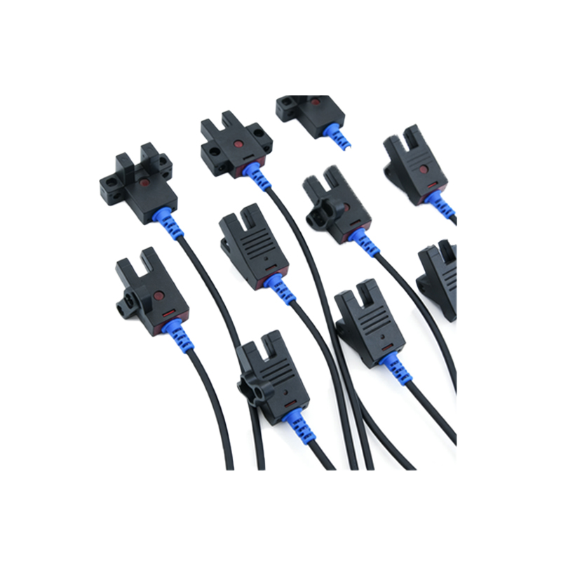
Photoelectric sensors operate by emitting a light beam and detecting changes in its intensity or interruption. In rotational applications, a slotted disk or reflective mark is attached to the rotating shaft. As the shaft rotates, the sensor generates pulses corresponding to each slot or mark. The frequency of these pulses directly correlates with angular velocity, enabling precise measurement of rotational speed. This non-invasive approach eliminates friction errors common in traditional methods, making it ideal for sensitive electrical components.
Measurement Setup and Equipment
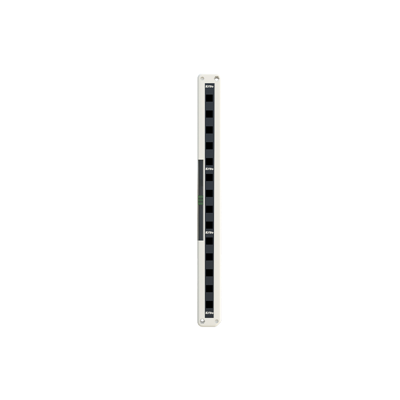
To measure moment of inertia, engineers require a photoelectric sensor, a data acquisition system, a known torque source (e.g., a calibrated motor), and a test object mounted on a low-friction bearing. The sensor is aligned with a slotted disk fixed to the shaft. A typical setup uses a through-beam or reflective sensor with a response time under 1 microsecond to capture high-speed rotations. The data acquisition system records pulse counts over time, which are then processed to derive angular acceleration.
Calculation Methodology
The moment of inertia (I) is derived from the relationship between torque (τ) and angular acceleration (α): I = τ / α. First, apply a known torque to the shaft using a motor or weight-and-pulley system. The photoelectric sensor measures angular velocity (ω) by counting pulses per second. Angular acceleration is calculated from the slope of ω versus time, typically using a linear regression over a stable rotation period. For example, with a torque of 0.5 Nm and an acceleration of 2 rad/s², I equals 0.25 kg·m². Multiple trials improve accuracy.
Practical Considerations
Engineers must account for factors like sensor alignment, ambient light interference, and bearing friction. Place the sensor at a fixed distance from the disk, typically 5-10 mm, to avoid signal loss. Use a dark enclosure to shield from ambient light. Calibrate the sensor with a known inertia standard before testing. Additionally, ensure the data acquisition rate is at least double the expected pulse frequency to avoid aliasing, following the Nyquist criterion.
Advantages in Electrical Engineering
Photoelectric sensors provide high precision, typically within 0.1% of the true value, and operate without physical contact, reducing wear. They are compatible with automated systems, allowing real-time monitoring. This method is particularly useful for testing electric motor rotors or flywheels in industrial settings, where repeatability and non-destructive testing are paramount. The technique also supports dynamic analysis, such as measuring inertia changes under load.
Example Application
Consider a brushless DC motor rotor with unknown inertia. Attach a 60-slot disk and apply a torque of 0.8 Nm. The sensor records 1200 pulses per second at steady state, translating to 20 rotations per second (since 1200/60 = 20 Hz). Angular velocity is 125.66 rad/s (20 Hz × 2π). If acceleration is 3 rad/s², the moment of inertia is 0.267 kg·m². This data helps engineers optimize motor control algorithms.
Conclusion
Photoelectric sensors provide a robust, accurate method for measuring moment of inertia in electrical engineering applications. By minimizing mechanical errors and enabling automation, this technique enhances reliability in design and testing. Engineers should follow proper setup and calibration to achieve optimal results, ensuring long-term performance in rotating systems.