2026-06-11
Tech Hub
By 创始人
Understanding the Key Specifications of Through-Beam Photoelectric Sensors for Industrial Applications
Introduction to Through-Beam Photoelectric Sensors
Through-beam photoelectric sensors are widely used in industrial automation for detecting objects without physical contact. They consist of a separate emitter and receiver, positioned opposite each other. When an object interrupts the light beam between them, the sensor triggers an output signal. This design offers high reliability, long sensing ranges, and immunity to ambient light interference, making them ideal for harsh environments in manufacturing, packaging, and material handling systems.
Key Specifications: Sensing Range and Beam Type
The sensing range is a critical parameter, typically ranging from a few meters to over 30 meters for through-beam sensors. Unlike retroreflective or diffuse sensors, through-beam sensors achieve the longest sensing distances due to direct line-of-sight between emitter and receiver. The beam type is usually infrared (IR), visible red, or laser. IR beams are common for general applications, while visible red aids alignment. Laser beams provide pinpoint accuracy for small object detection and high-speed processes. Engineers must match the range to the application's distance and environmental factors like dust or fog, which can attenuate the beam.
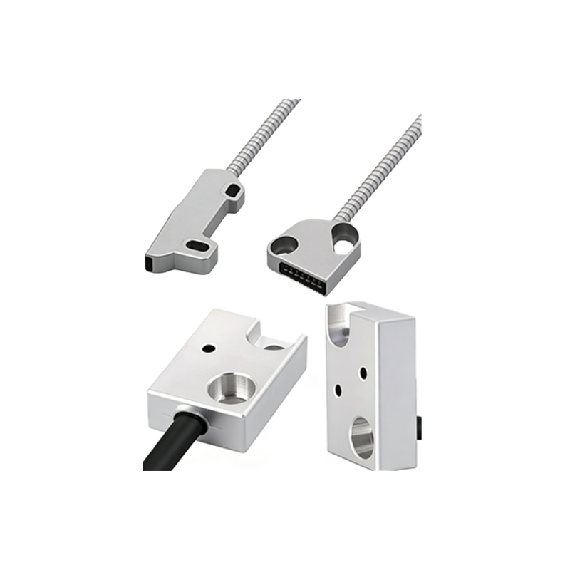
Response Time and Switching Frequency
Response time defines how quickly the sensor detects a state change, often measured in microseconds (µs) or milliseconds (ms). For fast-moving objects on conveyor belts, a response time of less than 1 ms is essential. Switching frequency, expressed in Hertz (Hz), indicates the maximum number of on-off cycles per second. High-frequency sensors (e.g., 10 kHz) are suitable for counting small parts in high-speed lines. Slower sensors (e.g., 100 Hz) suffice for bulk detection. These specs directly impact throughput and precision in automated systems.
Output Type and Electrical Characteristics
Common output types include NPN (sinking) or PNP (sourcing) transistor outputs, often with open-collector configurations. For PLC integration in North America, PNP is typical, while NPN is common in Asia. Some sensors offer analog outputs (0-10 V or 4-20 mA) for distance measurement. Supply voltage is usually 10-30 VDC, with low current consumption (e.g., 20-50 mA). Engineers must verify compatibility with the control system and consider load resistance for analog outputs. Additionally, protection features like reverse polarity and short-circuit protection enhance durability.
Environmental Ratings: IP Rating and Temperature Tolerance
The Ingress Protection (IP) rating, such as IP67 or IP68, indicates resistance to dust and water. IP67 is standard for washdown environments in food processing, while IP68 allows submersion. Operating temperature range (e.g., -25°C to 55°C) is vital for outdoor or extreme industrial settings. Some sensors have built-in heaters for cold climates. Material housing (e.g., stainless steel or polycarbonate) affects chemical resistance. For example, in automotive paint shops, sensors must resist solvents. Select ratings based on the facility's cleanliness and temperature extremes.
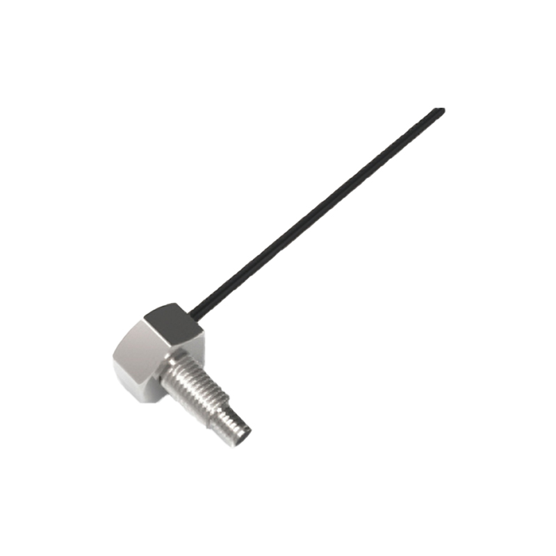
Alignment and Installation Considerations
Precise alignment of the emitter and receiver is crucial for through-beam sensors, as misalignment reduces sensitivity. Many models include visible red LEDs for visual alignment aids. The beam divergence angle (e.g., 1° to 5°) affects tolerance to misalignment. Wide-angle beams are easier to align but may cause false triggers from nearby objects. Installers should use brackets with adjustment slots. Additionally, consider cable length (e.g., 2 m standard, extendable to 100 m with proper shielding) and connector types like M12 or pigtail leads for robust connections in vibration-prone areas.
Application-Specific Selection Criteria
For detecting transparent objects like glass or plastic bottles, through-beam sensors with polarized light or specific wavelengths prevent false triggers. In dusty environments, choose sensors with automatic gain control (AGC) to compensate for signal loss. For safety applications, select sensors with built-in self-diagnostics and redundant outputs to meet SIL (Safety Integrity Level) standards. Always review datasheets for hysteresis and repeatability specs to ensure consistent performance. Prototyping in a test setup can validate the chosen sensor before full deployment.