Introduction to Through-Beam Photoelectric Sensors in Speed Measurement
Through-beam photoelectric sensors are widely used in industrial automation for non-contact detection of objects. When configured properly, they can accurately measure and adjust rotational speed (RPM) of rotating machinery such as motors, conveyors, and spindles. This article provides a step-by-step technical guide for engineers on using these sensors to tune speed, focusing on practical setup, signal processing, and calibration.
Sensor Selection and Mounting Considerations
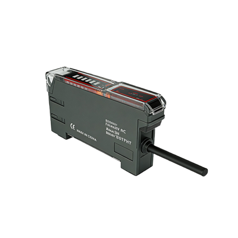
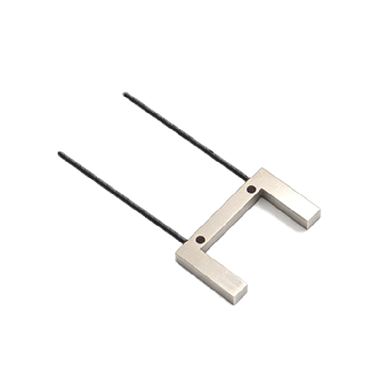
For RPM adjustment, select a through-beam sensor with a fast response time (e.g.,<1 ms) and a sensing range suitable for your application. Mount the emitter and receiver on opposite sides of the rotating shaft or target. Use a reflective tape or a slotted disk on the shaft to create alternating light and dark intervals. Ensure alignment is precise: misalignment can cause false triggers. The target should have a consistent width to generate uniform pulses. For high-speed applications, consider using a sensor with a high switching frequency (e.g., 10 kHz).
Signal Acquisition and Pulse Generation
Connect the sensor output to a PLC, frequency counter, or microcontroller. As the shaft rotates, the sensor produces a square wave signal: high when light is blocked (target present) and low when light passes through. Each complete rotation generates a number of pulses equal to the number of slots or marks on the target. For example, a disk with 60 slots yields 60 pulses per revolution (PPR). Record this pulse train for frequency analysis.
Frequency-to-RPM Conversion Formula
The fundamental formula for converting pulse frequency to rotational speed is:
RPM = (Frequency in Hz × 60) / PPR
Where:
- Frequency = number of pulses per second (from sensor output)
- PPR = pulses per revolution (slot count)
Example: If the sensor outputs 500 Hz and you have 60 PPR, then RPM = (500 × 60) / 60 = 500 RPM. Adjust PPR for higher resolution: use more slots for low-speed applications to improve accuracy.
Calibration and Error Correction
Calibration is critical for precise speed adjustment. Perform these steps:
1. Use a tachometer to measure actual RPM at a known reference speed.
2. Calculate the theoretical RPM from sensor pulses.
3. Adjust the PPR value in your code to match actual RPM.
4. Account for sensor jitter or noise by averaging multiple readings (e.g., over 1 second).
5. For varying loads, implement a moving average filter to smooth the output.
Feedback Control for Speed Adjustment
To actively adjust speed, integrate the sensor into a closed-loop control system. Compare the measured RPM (from sensor) to a setpoint. Use a PID controller to adjust motor drive parameters (e.g., voltage, frequency). The sensor provides real-time feedback: if RPM drops below setpoint, increase drive output; if overshoot occurs, reduce it. Set the loop update rate to at least 10x the expected mechanical response time.
Practical Troubleshooting Tips
Common issues include:
- Signal dropout due to dust or vibration: clean lenses and use vibration-damping mounts.
- False pulses from stray light: shield the sensor pair.
- Inconsistent pulse width: ensure target edges are sharp.
- Frequency drift: check for temperature effects on sensor electronics.
Always verify with an oscilloscope to visualize the waveform before connecting to control logic.
Conclusion
Through-beam photoelectric sensors offer a reliable, non-invasive method for rotational speed adjustment in industrial systems. By careful selection, proper mounting, and calibration, engineers can achieve high accuracy RPM control. Implement feedback loops for dynamic adjustments, and always validate with secondary measurements. This approach enhances machine performance and reduces downtime.