Introduction to Photoelectric Switch Sensors for Speed Measurement
As an electrical engineer specializing in industrial automation, I often rely on photoelectric switch sensors for non-contact rotational speed measurement. These sensors, also known as through-beam, retro-reflective, or diffuse sensors, are ideal for detecting rotating targets like shafts, gears, or encoder disks. The principle is straightforward: the sensor emits a light beam, and each interruption or reflection generates a pulse. By counting these pulses over time, we calculate RPM (revolutions per minute). This method offers high accuracy, minimal wear, and compatibility with harsh environments.
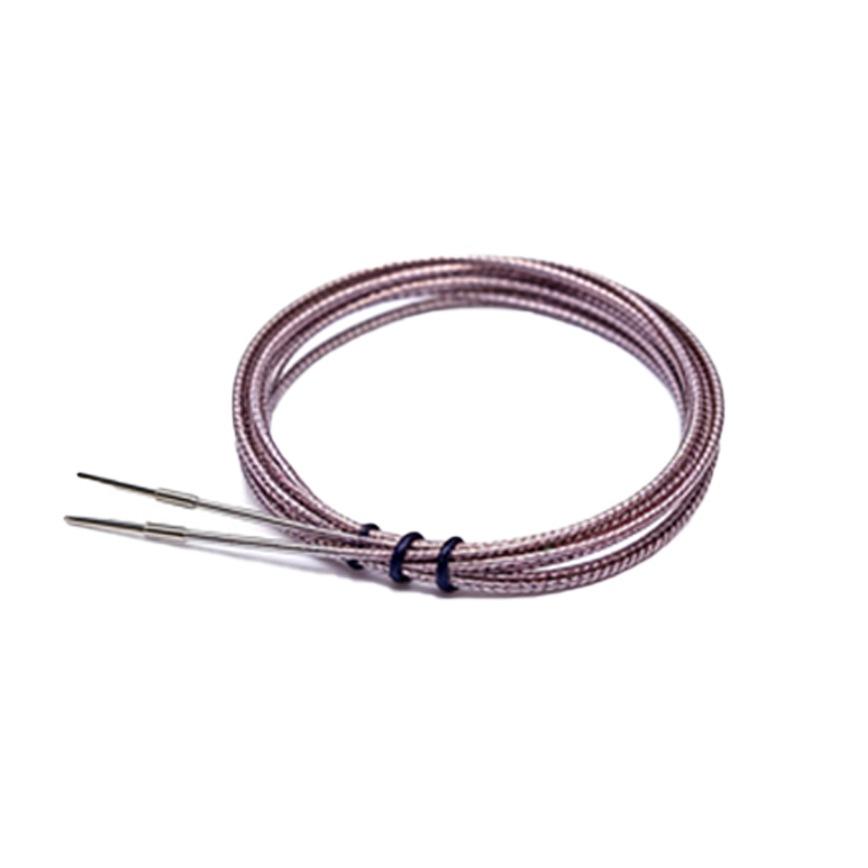
Key Components and Configuration
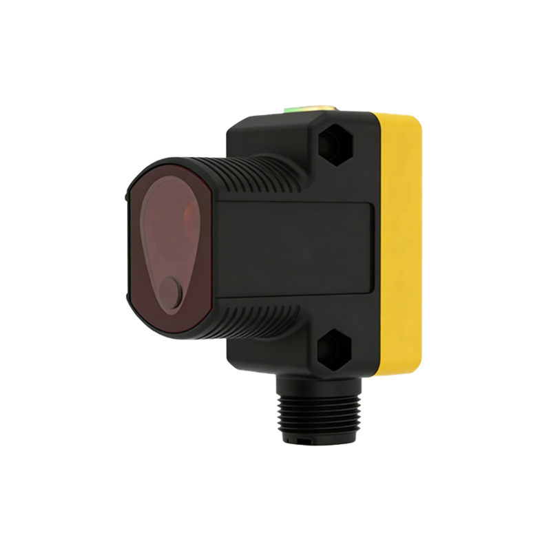
For speed measurement, select a sensor with a fast response time (e.g., 1 ms or less) and a suitable sensing range. For a rotating shaft, attach a flag or tape with contrasting reflective properties. Alternatively, use a slotted disk or gear teeth as the target. Connect the sensor output to a PLC, frequency counter, or microcontroller. Use a pull-up resistor if the output is open-collector. Calibrate by measuring the number of pulses per revolution (PPR). For a gear with 60 teeth, each revolution yields 60 pulses, simplifying RPM calculation: RPM = (Pulse Frequency / PPR) × 60.
Practical Wiring and Signal Processing

Wire the sensor’s power supply (typically 10-30 VDC) and output. For NPN sensors, the output sinks to ground when triggered; for PNP, it sources voltage. Use shielded cables to reduce electrical noise, especially near motors or inverters. In the PLC, program a high-speed counter input to capture pulses. Apply a debounce filter (e.g., 1 ms) to eliminate false triggers from vibration. For accurate low-speed measurements, extend the sampling time to 1 second or more. For high speeds, ensure the sensor’s switching frequency exceeds the expected pulse rate (e.g., 10 kHz for 6000 RPM with 100 PPR).
Calibration and Accuracy Considerations
Calibrate the system by manually rotating the shaft one full revolution and verifying the pulse count. Account for target geometry: a narrow flag may produce shorter pulses, requiring a sensor with a fast response. Temperature variations can affect sensor performance; use sensors rated for -25°C to 55°C. For precise applications, compensate for sensor’s hysteresis (typically 10% of the sensing distance). Validate accuracy with a tachometer. Example: a 10 Hz pulse rate with 20 PPR equals 30 RPM. If the sensor has a 0.5 ms response time, it can measure up to 2000 RPM with 60 PPR reliably.
Troubleshooting Common Issues
If the pulse count is erratic, check for alignment misalignment, dirt on the lens, or ambient light interference. Use a retro-reflective sensor with a polarizing filter to avoid false triggers from shiny surfaces. For low-speed measurement, ensure the target passes through the beam for at least the sensor’s minimum on-time (e.g., 0.5 ms). In high-vibration environments, mount the sensor on a rigid bracket. If using a diffuse sensor, the target’s color and reflectivity matter: white tape on a black shaft works best. Always test with a known RPM source before final commissioning.
Conclusion and Best Practices
Photoelectric switch sensors are a reliable, cost-effective solution for RPM measurement in industrial settings. Choose the correct sensor type for your target, configure the signal processing correctly, and perform regular maintenance. To optimize performance, use a sensor with a fast response time, adequate PPR, and proper shielding. This approach ensures accurate speed monitoring for conveyor belts, motors, and rotating machinery, enhancing both safety and process control.