1. Introduction to Micro Photoelectric Sensors
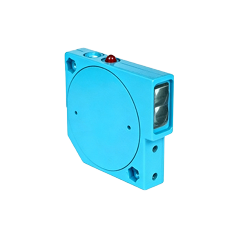
Micro photoelectric sensors are compact devices widely used in industrial automation for detecting objects, positions, and distances. They operate based on light emission and reception, typically using an LED and a photodetector. The schematic design is critical for ensuring reliable performance in environments with dust, vibration, or temperature variations. For engineers, understanding the core components—emitter, receiver, and signal processing unit—is essential for customization and troubleshooting.
2. Basic Schematic Architecture
The fundamental schematic includes a power supply, an LED driver circuit, a phototransistor or photodiode, and a comparator. The LED driver often uses a constant current source to maintain stable light output. The receiver converts light intensity into a voltage signal, which is fed into a comparator with a reference threshold. A typical circuit uses an operational amplifier (op-amp) in a non-inverting configuration to amplify weak signals. Resistor-capacitor (RC) filters are added to reduce noise from ambient light or power fluctuations.
3. Key Components and Their Functions
- LED Emitter: Infrared or visible light LEDs are chosen based on detection range and object reflectivity. The schematic includes a series resistor to limit current, often calculated using Ohm’s law (R = (V_supply – V_LED) / I_LED).
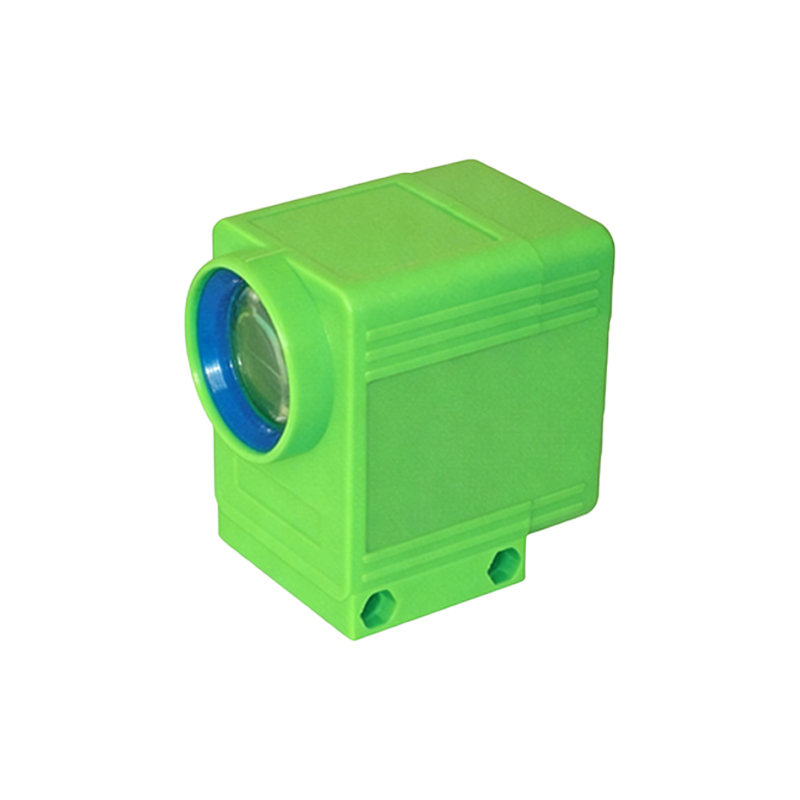
- Photodetector: Phototransistors offer high sensitivity but slower response, while photodiodes provide faster switching. The collector-emitter voltage drop in phototransistors is monitored by the subsequent stage.
- Comparator (e.g., LM393): Compares the photodetector output with a adjustable threshold voltage set by a potentiometer. The output goes high or low based on detection status.
- Output Stage: A transistor or MOSFET driver ensures compatibility with PLCs or microcontrollers. Pull-up resistors are common for open-collector outputs.
4. Signal Conditioning and Noise Mitigation
Ambient light interference is a common challenge. The schematic often incorporates a modulated LED drive (e.g., 1 kHz pulse) with a synchronous demodulator in the receiver. This requires an oscillator circuit (e.g., using a 555 timer) to generate pulses. Additionally, a Schmitt trigger can clean up the comparator output, preventing false triggers from noise. Capacitors placed across power rails stabilize the supply voltage.
5. Practical Implementation Example
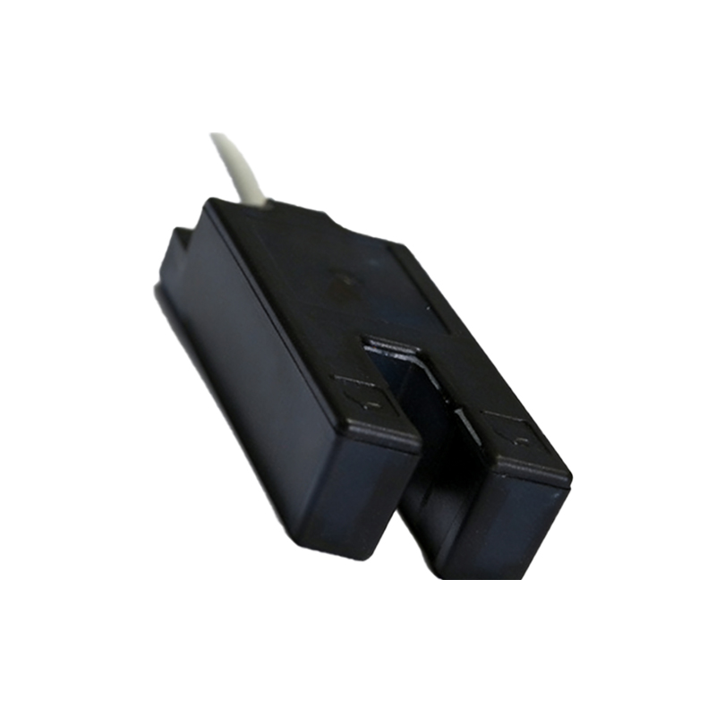
Consider a through-beam sensor: The emitter and receiver are aligned physically. The schematic shows a 5V supply to both modules. The emitter uses a 100-ohm resistor in series with an IR LED. The receiver uses a photodiode reverse-biased at 5V, connected to a transimpedance amplifier (e.g., OPA381) with a 1 MΩ feedback resistor. The amplified signal enters a comparator with a 2.5V reference. When the beam is broken, the output drops to 0V, triggering an alarm. Engineers should test the circuit with an oscilloscope to verify timing and sensitivity.
6. Troubleshooting Common Schematic Issues
- No Output: Check power polarity, LED continuity, and photodetector bias. Use a multimeter to measure voltage at key nodes.
- False Triggers: Increase the threshold voltage or add a low-pass filter (e.g., 10kΩ resistor and 1µF capacitor) at the comparator input.
- Slow Response: Replace phototransistor with a faster photodiode and adjust the feedback resistor value. Ensure the comparator has hysteresis (e.g., 1% positive feedback).
7. Advanced Design Considerations
For high-speed applications (e.g., counting at 10 kHz), use a photodiode with a transimpedance amplifier and a high-speed comparator like LMV7219. Include a voltage regulator (e.g., LM7805) to isolate noise from the main power supply. PCB layout should keep signal traces short and separate from power lines. A ground plane reduces electromagnetic interference (EMI). Simulation tools like SPICE can validate the schematic before prototyping.