Introduction to Photoelectric Sensors and Power Supply Requirements
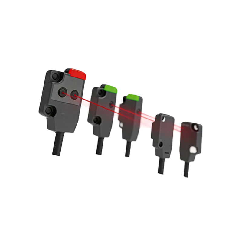
Photoelectric sensors are fundamental components in modern industrial automation, utilized for object detection, counting, and positioning. Typically, these sensors are designed to operate within a specific voltage range, commonly 12V DC to 24V DC. The question of whether a photoelectric sensor can be powered with a 6V DC supply arises in scenarios where power constraints or existing systems dictate lower voltage availability. As an electrical engineer, it is crucial to evaluate the technical feasibility, performance implications, and safety considerations before implementing such a configuration.
Technical Feasibility: Can a Photoelectric Sensor Run on 6V DC?
The answer is conditional. Many photoelectric sensors have a specified operating voltage range, often printed on the sensor label or in the datasheet. For example, standard models from brands like Omron, SICK, or Banner typically require a minimum of 10V DC to 30V DC. Applying 6V DC to such sensors will result in insufficient power, leading to unstable operation, failure to emit a reliable light beam (for through-beam or reflective types), or no output signal at all. However, some specialized low-power sensors or those designed for battery-operated systems may accept 6V DC. Always consult the manufacturer’s datasheet for the exact voltage tolerance. A 6V DC supply may work with older or custom-designed sensors, but it is not recommended for standard industrial applications due to the risk of degraded performance.
Performance Implications of Using 6V DC
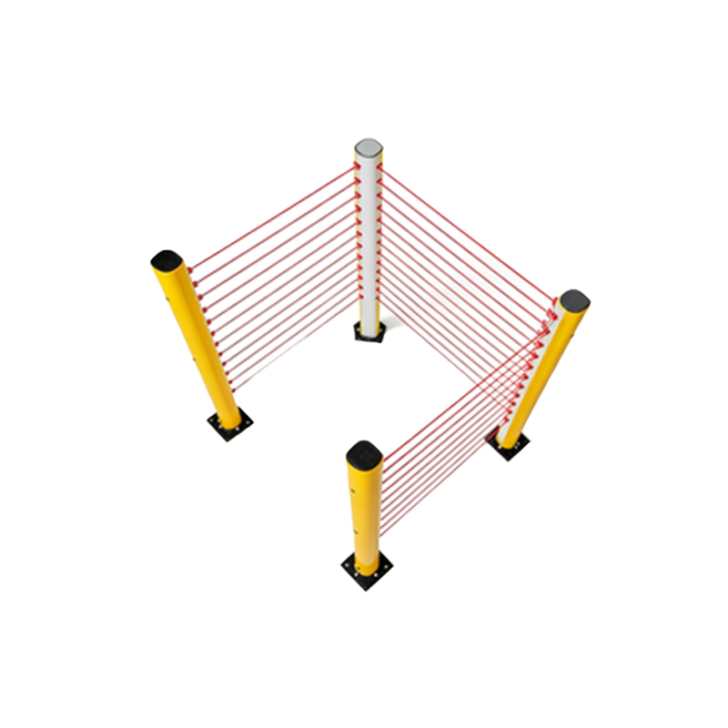
If the sensor is capable of operating at 6V DC, the performance will likely be suboptimal. Key parameters affected include sensing distance, response time, and output signal strength. For instance, a sensor rated for 24V DC might exhibit a 30% reduction in sensing range when powered at 6V, as the emitter LED’s intensity decreases with lower voltage. Additionally, the receiver circuit may have reduced sensitivity, making the sensor prone to false triggers or missed detections, especially in dusty or bright ambient light conditions. The output stage, whether NPN or PNP, may also fail to drive loads correctly, resulting in logic errors in the PLC or controller. In critical safety applications, such as guard monitoring, using a non-compliant power supply could pose significant risks.
Circuit and Wiring Considerations for 6V DC Operation
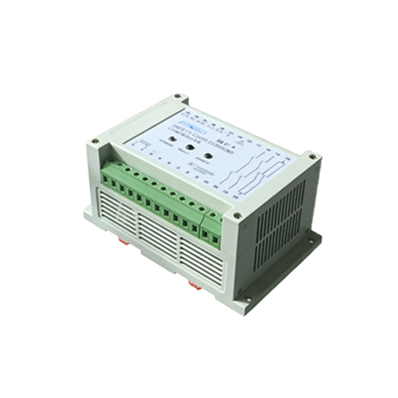
When attempting to use a 6V DC supply, the wiring must be carefully checked. Most photoelectric sensors have internal voltage regulators or zener diodes that clamp the voltage to a stable internal level. If the input voltage drops below the dropout voltage of these regulators, the sensor’s internal electronics may shut down or enter a brownout state. For sensors with built-in short-circuit protection, the protection circuits might also malfunction under low voltage. Ensure that the 6V DC source is well-regulated and has sufficient current capacity, typically 50-200 mA per sensor. Use a multimeter to verify the voltage at the sensor terminals, accounting for voltage drops across long cable runs. In some cases, a DC-DC boost converter can step up 6V DC to the sensor’s required voltage, but this adds complexity and cost.
Alternative Solutions and Best Practices
To avoid performance issues, consider using a dedicated power supply that meets the sensor’s nominal voltage. If a 6V DC system is unavoidable, select sensors explicitly rated for low voltage, such as 3V to 12V DC models from manufacturers like Panasonic or Autonics. Alternatively, use a voltage regulator module to convert the 6V DC to the sensor’s required level. For new installations, always design the power system around the sensor specifications, not the other way around. Document the voltage tolerance in the system design to prevent miswiring during maintenance. As a rule of thumb, never exceed the maximum voltage rating, and avoid operating below the minimum voltage specified in the datasheet.
Conclusion: Practical Recommendations for Engineers
In summary, while some photoelectric sensors may technically operate on 6V DC, it is generally not advisable for reliable industrial applications. The risks of compromised performance, reduced lifespan, and system instability outweigh the potential benefits. As an electrical engineer, prioritize using sensors within their specified voltage range, and when in doubt, perform a controlled test with the actual 6V supply under typical operating conditions. Always refer to the manufacturer’s technical documentation and consider factors like ambient temperature and electrical noise. By adhering to these guidelines, you ensure robust and safe automation systems.