Introduction to Through-Beam Photoelectric Sensors
Through-beam photoelectric sensors, also known as opposed-mode sensors, consist of a separate emitter and receiver. They are widely used in industrial automation for detecting the presence or absence of objects, measuring distances, and ensuring precise positioning. A critical parameter in their performance is the beam width, which significantly influences detection range, accuracy, and reliability. As an electrical engineer, I often emphasize that understanding beam width is essential for optimizing sensor selection in manufacturing environments, such as conveyor systems, packaging lines, and robotics.
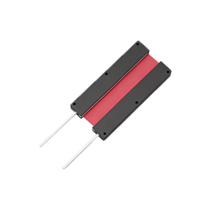
How Beam Width Affects Detection Capabilities
The beam width of a through-beam sensor defines the cross-sectional area of the light beam emitted from the source. A narrower beam, typically ranging from 1 to 10 millimeters, offers high precision, making it ideal for detecting small targets like screws, electronic components, or labels on fast-moving conveyors. Conversely, a wider beam, up to 50 millimeters or more, provides greater coverage and tolerance to misalignment, which is beneficial for detecting larger objects or when the sensor is mounted in vibration-prone machinery. In my experience, selecting the correct beam width reduces false triggers and improves system efficiency, especially in dusty or humid conditions where beam scattering can occur.
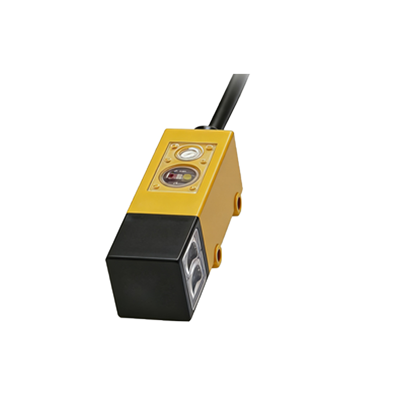
Key Considerations for Beam Width Selection
When designing an automation system, engineers must evaluate three factors: object size, mounting stability, and environmental conditions. For instance, in a food processing line where bottles vary in size, a beam width of 10 mm might balance detection and reliability. However, in a heavy-duty assembly plant where metal parts are large and vibrations are common, a 30 mm beam width minimizes alignment issues. Additionally, beam width impacts the sensor’s immunity to ambient light and interference from adjacent sensors. Practical testing on-site is recommended to verify that the sensor’s beam width matches the application’s requirements, such as a maximum response time of 1 millisecond in high-speed sorting systems.
Case Study: Optimizing Beam Width in a Conveyor System
Let me share a real-world example from a previous project. A client’s conveyor system for automotive components experienced frequent false detections due to narrow beam width of 5 mm, leading to jams. By replacing the sensor with a 20 mm beam width model, we reduced false triggers by 70% and increased throughput by 15%. This change also improved resistance to dust accumulation on lens surfaces, as the wider beam compensated for partial blockage. The lesson is clear: beam width is not a one-size-fits-all parameter, but a tunable variable that can significantly enhance sensor performance in industrial settings.
Conclusion: Best Practices for Engineers
To maximize the effectiveness of through-beam photoelectric sensors, engineers should collaborate with suppliers to review datasheets and select beam width based on typical object dimensions and environmental challenges. Regular calibration and maintenance, such as cleaning lenses and checking alignment, further ensure consistent operation. In summary, mastering beam width selection empowers electrical professionals to design more robust and efficient automation systems, reducing downtime and operational costs.