Understanding the Sources of Interference in Photoelectric Sensors
Photoelectric sensors are widely used in industrial automation for object detection, ranging, and counting. However, they are susceptible to various interference sources, including ambient light (sunlight, artificial lighting), electrical noise from motors and inverters, cross-talk from adjacent sensors, and environmental factors like dust, fog, or vibration. Understanding these sources is the first step in designing a robust system. For instance, strong ambient light can saturate the receiver, while electrical noise may cause false triggering. In practice, identifying the dominant interference type in your specific facility—such as high-frequency noise from welding equipment or stray reflections from shiny surfaces—allows you to tailor mitigation strategies effectively.
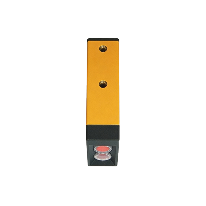
Optical Design and Shielding Techniques
One of the most direct approaches is to optimize the sensor's optical design. Use sensors with modulated light (e.g., pulsed LED or laser) rather than continuous wave, as modulation helps distinguish the sensor's signal from background light. Employ optical filters that match the sensor's emitter wavelength, reducing the impact of sunlight or other broad-spectrum sources. Physical shielding, such as installing hoods or tubes around the sensor head, can block direct ambient light and reduce false triggers from reflections. Additionally, using polarized or retro-reflective sensors can minimize errors from glossy or mirrored targets. For example, in a conveyor belt application, a polarized retro-reflective sensor can reliably detect transparent or shiny packages without interference from nearby surfaces.
Electrical Noise Suppression and Wiring Best Practices
Electrical interference, often from variable frequency drives (VFDs) or switching power supplies, can corrupt sensor signals. To mitigate this, use shielded cables with the shield grounded at one end to avoid ground loops. Keep sensor cables at least 20 cm away from high-voltage power cables or motor lines. Install ferrite cores or common-mode chokes on the sensor output lines to filter high-frequency noise. For sensors with digital outputs (PNP/NPN), ensure proper termination with pull-up or pull-down resistors to prevent floating states. In harsh environments, opt for sensors with built-in EMC protection, such as transient voltage suppressors (TVS) and filtering capacitors. A practical case is in a robotic cell where multiple sensors operate near servo drives—isolating sensor cables and using differential output (e.g., RS-485) can significantly reduce errors.
Environmental and Installation Strategies
Dust, moisture, and temperature variations can degrade sensor performance. Select sensors with IP67 or higher ratings for wet or dusty areas. Use air purge systems or wipers for sensor lenses to maintain clear optical paths. In high-temperature zones (e.g., near furnaces), choose sensors with heat-resistant housings or use fiber optic cables to remote the electronics. For outdoor applications, consider sensors with automatic gain control (AGC) to adapt to changing light conditions. Additionally, avoid mounting sensors where direct sunlight or reflections from machinery can cause false detection. For example, in a packaging line, positioning sensors at an angle relative to the target reduces the chance of specular reflections interfering with the signal.
Cross-Talk Prevention in Multi-Sensor Systems
When multiple photoelectric sensors operate in close proximity, cross-talk occurs when one sensor's emitter beam is detected by another sensor's receiver. To prevent this, use sensors with different modulation frequencies or employ synchronization if the sensor model supports it. Physically orient sensors so that their beams do not intersect, or install opaque barriers between them. In dense installations, such as a sorting system with dozens of sensors, assign unique frequency codes (e.g., using frequency-hopping or coded light) to ensure each sensor only responds to its own emitter. Alternatively, use sensors with narrow beam angles or focusing lenses to limit the detection zone.
Advanced Signal Processing and Software Filters
Modern photoelectric sensors often incorporate digital signal processing (DSP) to enhance noise immunity. Features like hysteresis, time-delay filters, and averaging algorithms can reject transient interference. For example, a sensor can be set to ignore pulses shorter than 5 ms, which helps filter out electrical spikes. In fieldbus systems (e.g., IO-Link), software-based filters can be adjusted remotely for dynamic environments. Additionally, using sensors with complementary outputs (both normally open and normally closed) allows the PLC to cross-check signals for consistency. A real-world application is in a high-speed bottling line, where a sensor with a moving-average filter reliably detects bottles despite vibration from the conveyor.
Regular Maintenance and Calibration
Even with the best design, performance degrades over time. Establish a routine maintenance schedule: clean sensor lenses with alcohol-free wipes, check cable connections for corrosion, and verify alignment against the target. Use a calibration tool or a known reference object to ensure the sensor's sensitivity and threshold settings remain optimal. Document environmental changes (e.g., new machines installed nearby) that could introduce interference. For critical applications, implement redundant sensors with diagnostic outputs to alert operators of impending failures. A preventive approach, such as quarterly inspections in a metal stamping plant, can minimize downtime and false detections.